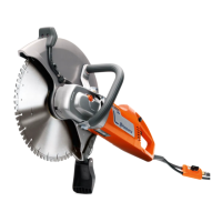
Do you have a question about the Husqvarna K1270 and is the answer not in the manual?
Overview of the workshop manual's purpose and content.
Essential safety precautions and warnings for repair work.
Identifies the intended audience for the workshop manual.
Explains how product modifications affect service information.
Information on special tools required for specific repair stages.
Describes how the workshop manual is organized for use.
Explains the designation of position references and figure numbers.
General guidelines for workshop safety and manual adherence.
Details hazardous properties of fuel and specific safety advice.
Explains symbols found on the machine for controls and functions.
Explains warning symbols used within the manual for safety.
Compares technical design variations between K1260 and K1270 models.
Details bearing types for K1260 and K1270 clutch drums.
Outlines steps for dismantling the blade guard for K1260 and K1270.
Explains differences in air filter covers for K1260 and K1270.
Describes differences in rear belt guards for K1260 and K1270.
Labels and identifies various parts of the machine with a diagram.
Introduces the concept of breaking down the machine into fundamental components.
Step-by-step instructions for dismantling the starter assembly.
Procedures for dismantling the cutting head and related components.
Instructions for removing and handling the cutting arm.
Steps for removing and servicing the air filter.
Instructions for removing the cylinder cover.
Procedures for dismantling and accessing the carburettor.
Steps for removing the air duct assembly.
Instructions for dismantling and removing the muffler.
Procedures for removing the inlet manifold.
Steps for dismantling and removing the inlet nozzle.
Guidance on separating the machine at anti-vibration elements.
Detailed steps for replacing the starter cord.
Procedures to safely release tension from the return spring.
Instructions for fitting and securing a new starter cord.
Steps for correctly winding and fitting the return spring.
Instructions for dismantling the return spring assembly.
Explains the function, inspection, and assembly of starter pawls.
Explains the operational principles of the ignition system.
Details the ignition module, its connections, and maintenance requirements.
Information on spark plug gap, cleaning, and replacement.
Guides on diagnosing and resolving ignition system issues.
Step-by-step process for removing the flywheel.
Explains the centrifugal cleaning process in the air intake.
Procedures for cleaning the intake and replacing the paper filter.
Instructions for dismantling and assembling the inlet manifold.
Guidance on dismantling, checking, and replacing the fuel filter.
Procedures for testing the fuel system for leaks using a pressure tester.
Steps for checking the integrity of the fuel hose.
Explains the function and dismantling of the tank aeration unit.
Methods for testing the function of the tank valve.
Procedure for testing the sintered filter's airflow.
Instructions for replacing a clogged fuel filter.
Identifies and labels the various parts of the carburettor.
Discusses different carburettor versions and common service components.
Procedures for functional testing of the carburettor, including pressure tests.
Method for checking external leakage and needle valve function using water.
Instructions for testing the pump diaphragm for leaks.
Information on inspecting the measurement chamber diaphragm.
Explains the function and chambers of the measurement chamber.
Visual inspection guidelines for the measurement chamber diaphragm.
Troubleshooting and procedures for the needle valve, a common cause of malfunction.
Guidance on inspecting needle tip wear using magnification.
Steps for cleaning the needle valve seating.
Explains the operational principle of the carburettor's pump unit.
How to visually inspect the pump unit's valve flaps for proper function.
Guidance on inspecting, cleaning, and replacing the fuel strainer.
Instructions for cleaning internal carburettor channels with compressed air.
Checking valve axles for play and potential wear.
Notes on factory-set carburettor nozzles and lack of adjustment needed.
Procedures for adjusting the engine's idle speed using special tools.
Explains how the decompression valve reduces starting compression.
Method to check the decompression valve for leaks without starting the engine.
Procedure for testing cylinder compression and interpreting results.
Steps for dismantling the cylinder from the engine.
Instructions for dismantling the piston, including circlips and gudgeon pin.
Method for dismantling and assembling piston rings, including alignment.
Guidance on inspecting components for wear and identifying causes of failure.
Specifications for measuring wear on cylinder, piston, and rings.
Identifies common types of piston damage and their causes.
Characteristics of normal wear on piston and rings.
Explains the effects of dust on engine components and how to identify it.
Describes damage caused by overheating and lack of oil.
Identifies signs of overheating on the piston top and potential causes.
Procedures for testing crankcase integrity for leaks.
Specific steps and expected results for crankcase leakage tests.
Instructions for dismantling and fitting crankcase sealing rings.
Steps for splitting the crankcase halves.
Procedures for replacing the main bearing.
Instructions for assembling the crankshaft into the crankcase.
Steps for removing the clutch assembly from the machine.
Specifications for clutch shoe height and clutch drum diameter.
Instructions for assembling the clutch assembly, including torque specifications.
Procedures for dismantling and cleaning clutch springs and shoes.
Detailed steps for replacing needle bearings in the clutch drum and belt pulley.
Instructions for dismantling the cutting head and blade guard.
Procedures for replacing bearings in the blade shaft housing.
Explains the basic design and function of the wet cutting system's spray nozzles.
Steps for removing and replacing spray nozzles.
Instructions for replacing the filter in the wet system.
Information on reusing and operating hose clips for the wet system.
Overview of controls located in the rear handle assembly.
Identifies components within the divided rear handle halves.
Emphasizes following a specific order for dismantling and assembly.
Instructions for dismantling the handle to change the throttle wire.
Procedures for removing and fitting the throttle lock mechanism.
Steps for removing the throttle unit from the handle.
Procedures for installing the throttle unit correctly.
Instructions for fitting and securing the throttle lock assembly.
Diagnosing and resolving issues when the engine fails to start.
Troubleshooting common causes for the engine stopping during operation.
Diagnosing why the engine may be difficult to stop.
Troubleshooting issues related to low power or unstable engine rotation.
Addresses other engine-related issues like clutch, vibration, and blade rotation.
| Engine Power | 5.8 kW |
|---|---|
| Weight | 13.7 kg |
| Sound Power Level, Guaranteed (LWA) | 117 dB(A) |
| Engine | 2-stroke |
| Power output | 5.8 kW |
| Blade Diameter | 350 mm / 400 mm |
| Max Cutting Depth | 125 mm / 145 mm |
| Guide bar length | Not Applicable |

