Do you have a question about the Hussmann Proto-Aire and is the answer not in the manual?
Provides essential information for setting up the Protocol™ Unit and references auxiliary equipment manuals.
Instructions for inspecting equipment for damage before and during unloading.
Procedure for noting obvious loss or damage on freight bills for carrier claims.
Process for filing claims for damage discovered after equipment is uncrated.
Guidance on safely removing panels to access lifting points on the unit frame.
Lists dimensions and weights for vertical Protocol™ units.
Provides dimensions and weights for horizontal Protocol™ units.
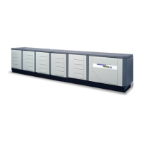
Details dimensions and weights for Proto-Aire™ units.
Specifies required clearance for servicing control panels and unit access.
Information on required field-supplied water loop components.
Instructions for removing panels from vertical units.
Instructions for removing panels from horizontal units.
Diagram illustrating typical piping and electrical connections for vertical units.
Details major refrigeration components and their locations within the piping system.
Guidelines for installing refrigeration tubing, brazing, and supporting lines.
Specifies the recommended return gas superheat range for all units.
Instructions for installing suction lines, including slope and reduction.
Guidance on take-offs from liquid lines and reducing line size.
Explains the refrigeration cycle, including components like oil separators and receivers.
Describes the setup and operation of 3-pipe gas defrost systems.
Information on implementing heat reclaim systems with Protocol™ units.
Explains the use of split suction for systems requiring two temperatures.
Details the refrigeration oil circulation and separation process.
Describes the process of liquid injection for cooling scroll compressors.
Explains the method of vapor injection for scroll compressor cooling.
Details major water loop components and their placement in the piping system.
General recommendations for water loop installation and maintenance.
Instructions for solvent welding PVC pipe and proper fitting connections.
Guidance on installing isolation valves at unit inlets, outlets, and throughout the system.
Requirement for a 16-mesh strainer at each Protocol™ unit inlet.
Recommendation for manual air vent valves at high points in the piping.
Correct method for connecting branch supply pipes to main supply headers.
Guidelines for spacing and type of pipe supports.
Advice on shading or covering piping exposed to direct sunlight.
Procedure for checking piping for leaks using pressurized water at 50 psig.
Steps for cleaning the pipe loop with a trisodium phosphate solution.
Requirements for filling the water loop with glycol for corrosion and freeze protection.
Instructions for adjusting flow balancing valves within each Protocol™ unit.
Details on presetting the flow control valve using the Bell & Grossett Circuit Setter.
General considerations for balancing the water loop.
Factors to consider when balancing water loops using direct return piping.
Explains how flow rate is proportional to circuit setter closure.
Methodology for balancing systems based on piping head loss and flow rate.
Guidance on connecting electrical field wiring to Protocol™ units.
Lists the largest connectable wire sizes for terminals based on total load amperes.
Information on checking legends for MCA, MOPD, and following NEC guidelines.
Details on wiring the remote alarm system and its connections.
Wiring requirements for temperature sensors and defrost termination thermostats.
Lists electrical circuits the Protocol™ can provide power for.
Explains power source for evaporator refrigeration solenoids.
Information on wiring door switch kits for liquid line solenoids and fans.
Lists the voltages present in the Protocol™ Control Panels.
Description of Alarm LEDs for preliminary troubleshooting.
Illustrates typical wiring for temperature sensors and Klixon devices.
Provides a legend for electrical symbols used in wiring diagrams.
Lists standard 120V components included in the Protocol™ system.
Details the 24V circuits used for control boards and POWERLINKS™.
Explanation of the 24V transformer powering the electronic oil level control.
Wiring diagram for PCS control and compressor wiring without vapor injection.
Wiring diagram for PCS control and compressor wiring with vapor injection.
Wiring diagram for CPC, Danfoss control without vapor injection.
Wiring diagram for CPC, Danfoss, Comtrol control with vapor injection.
Details PCS controller wiring, including communication and terminal points.
Wiring diagrams for CPC controllers, including optional leak detection.
Wiring diagrams for CPC Einstein controllers, including optional leak detection.
Wiring diagrams for Danfoss controllers, factory and field installed.
Wiring diagrams for Comtrol controllers, factory and field installed.
Shows electrical connections during the refrigeration cycle.
Explains the sequence of operation for defrost control.
Describes the sequence for off-time defrost termination.
Details the operation of hot gas defrost systems.
Explains the application and operation of electric defrost.
Interlocking heat reclaim with hot gas defrost systems.
Procedure for filling the closed loop system with glycol.
Steps for leak testing and evacuation of the refrigeration system.
Visual inspection of lines and joints for proper piping practices.
Procedure for checking compressor rotation and phase alignment.
Includes checking superheat, settings, and field piping.
Diagnosing and resolving high suction pressure alarms.
Diagnosing and resolving low suction pressure alarms.
Diagnosing and resolving alarms when all compressors are off.
Steps for preparing and replacing a compressor.
Procedure for shutting down, isolating, and replacing the drier.
Schedule for recommended maintenance tasks for Protocol™ systems.
Maintenance tasks to be performed every six months.
Maintenance tasks to be performed annually.
Maintenance tasks to be performed every two years.
| Brand | Hussmann |
|---|---|
| Model | Proto-Aire |
| Usage | Commercial |
| Cooling Technology | Forced Air |
| Type | Refrigerator |
| Refrigerant | R-404A |