Do you have a question about the Huvitz CRK-8800 and is the answer not in the manual?
General overview of safety, warnings, notes, and cautions for equipment operation.
Explanation of IEC safety symbols used for medical electronic equipment and potential hazards.
Guidelines for avoiding adverse environments for operation and storage of the equipment.
Detailed precautions for safe operation, handling, and maintenance of the equipment.
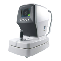
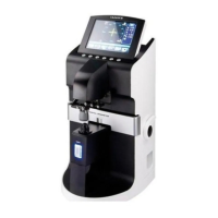
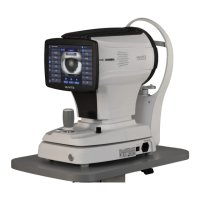
Identification and description of the main physical components of the Auto Ref/Keratometer.
Diagram and list of optical components within the Auto Ref/Keratometer.
Detailed list of all optical components with their corresponding numbers and functions.
Explanation of the different light paths within the optical system for various functions.
System functional block diagram illustrating the electrical connections and components.
Block diagram detailing the power input and distribution within the equipment.
Diagram showing the wiring connections on the Main Board of the device.
Diagram of the Base IO Interface Board with connector layout.
Details of wire harness connections for the IO Board.
Layout diagram and harness connections for the Motor interface board.
Visual representation of the Main Board PCB with labeled components.
Explanation of how refractometry measurements are performed using light and camera.
Details on how keratometry measurements are conducted using ring light projection.
Explains how incident light is scattered back for observation of eye structures.
Procedures for checking and controlling the equipment's operational status.
Steps to change the unit of measurement for refractometry data to 0.01.
Procedure to find and set the '0D' position for the eye fixation target.
Guide to verifying the stored setup data for the REF model eye.
Steps to adjust and re-measure REF data to ensure accuracy within tolerance.
Procedure for checking the stored setup data for the KER model eye.
Process to adjust KER data for accuracy within measurement tolerance.
Procedure for adjusting parameters for the auto start function of the device.
Instructions for upgrading the device's Operating System program.
General guidelines for safely disassembling and reassembling the equipment.
Steps to remove the outer covers and head rest assembly.
Procedure to remove the first part of the optical head assembly.
Procedure to remove the second part of the optical head assembly.
Steps to remove the base, moving base, PD Encoder, and PI Sensor Assy.
Procedure to remove Y-Pole, User Lock, Joystick, and PD Assy.
Steps to remove the fixing base assembly.
Troubleshooting common electrical issues like power lamp not lighting.
Troubleshooting issues with the LCD monitor display, such as brightness or movement.
Troubleshooting common measurement errors and failures.
Troubleshooting common printer issues like no printing or paper feed errors.
Troubleshooting for miscellaneous issues not covered in other categories.
Explanation of the Fogging Method for measuring refractive power and reducing errors.
Explanation of Vertex Distance and its influence on refraction power correction.
Description of the three types of cylinder forms for displaying measurement data.
Explanation of how the axis is expressed counterclockwise from the ear side.
Definition of Pupillary Distance (PD) and average values for different genders.
How to print and interpret the eyeball diagram for REF measurement results.
| Corneal Refraction | Yes |
|---|---|
| Corneal Astigmatism | Yes |
| Axis | 0° to 180° |
| Measurement Resolution | 0.01D |
| Type | Auto Refractor Keratometer |
| Measurement Range (Cylindrical) | 0D to ±12D |
| Pupil Diameter Measurement Range | 2.0 mm to 8.0 mm |
| PD Measurement Range | 40 mm to 80 mm |
| Minimum Pupil Diameter | 2mm |
| Measurement Accuracy | ±0.25D |
| Display | LCD |
| Power Supply | AC 100V to 240V, 50/60Hz |