Do you have a question about the Huvitz HLM-7000 and is the answer not in the manual?
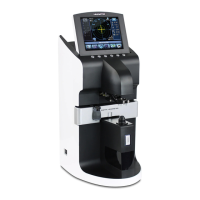
Identifies the main external parts of the lensmeter.
Outlines the general steps for lensmeter repair and troubleshooting.
Provides essential safety and handling guidelines for the instrument.
Explains the composition and function of the lensmeter's optical components.
Details the fundamental principles behind lens measurement.
Describes the sequence of operations for initial setup and mode entry.
Guides on calibrating the lensmeter's origin point for accurate measurements.
Instructions for calibrating prism settings using standard lenses.
Details the calibration process for diopter prism values.
Step-by-step guide for replacing the CCD camera module.
Procedure for replacing the LED assembly component.
Instructions for replacing the pinhole housing unit.
Explains how to safely remove external covers for access.
Details the process of taking apart the LCD assembly.
Steps for removing the printer module from the device.
Guide to disassembling the PD (Pupillary Distance) measurement assembly.
Procedure for removing the UV measurement components.
Instructions for disassembling the lens movement mechanisms.
Steps for removing and disassembling the gear mechanisms.
Procedure for removing the main electronic control board.
Guide to removing the main structural support assembly.
Instructions for removing power supply and related components.
Details the layout and components of the main circuit board.
Visual representation of the electrical system's connections and data flow.
Troubleshooting guide for the Switched-Mode Power Supply module.
Procedure for testing the functionality of the LCD display.
Steps for diagnosing and testing LED components.
Guide for testing the UV measurement module's performance.
Procedure for testing the PD measurement functionality.
Troubleshooting steps for the thermal printer.
Overview of the OS upgrading process and its benefits.
Detailed instructions for upgrading the OS using the DNW application.
| Minimum Pupil Diameter | 2.0 mm |
|---|---|
| Printer | Built-in thermal printer |
| Power Supply | AC 100-240V, 50/60 Hz |
| Vertex Distance | 12.0 mm |
| Sphere | -25.00D to +25.00D |
| Cylinder | 0 to ±8.00D |
| Axis | 0° to 180° |
| Pupil Distance | 45 to 82 mm |
| Measurement Time | 0.07 seconds |
| Corneal Curvature Radius | 5.0 ~ 10.2mm |
| Corneal Refraction | 30.00D to 67.50D |
| Display | LCD |
| Measurement Range (Spherical) | -25.00D to +25.00D |
| Measurement Range (Cylindrical) | 0 to ±8.00D |
| Measurement Accuracy (Spherical) | ±0.06D |
| Measurement Accuracy (Cylindrical) | ±0.25D |
| Pupillary Distance (PD) Measurement Range | 45 to 82 mm |
| Prism Measurement Range | 0 ~ 10Δ |