CVH8, HVH8, TVH8, VA9, HVA9, TVA9: APPLICATION GUIDELINE & SERVICE MANUAL
Manufacturer reserves the right to change, at any time, specifications and designs without notice and without obligations.
3
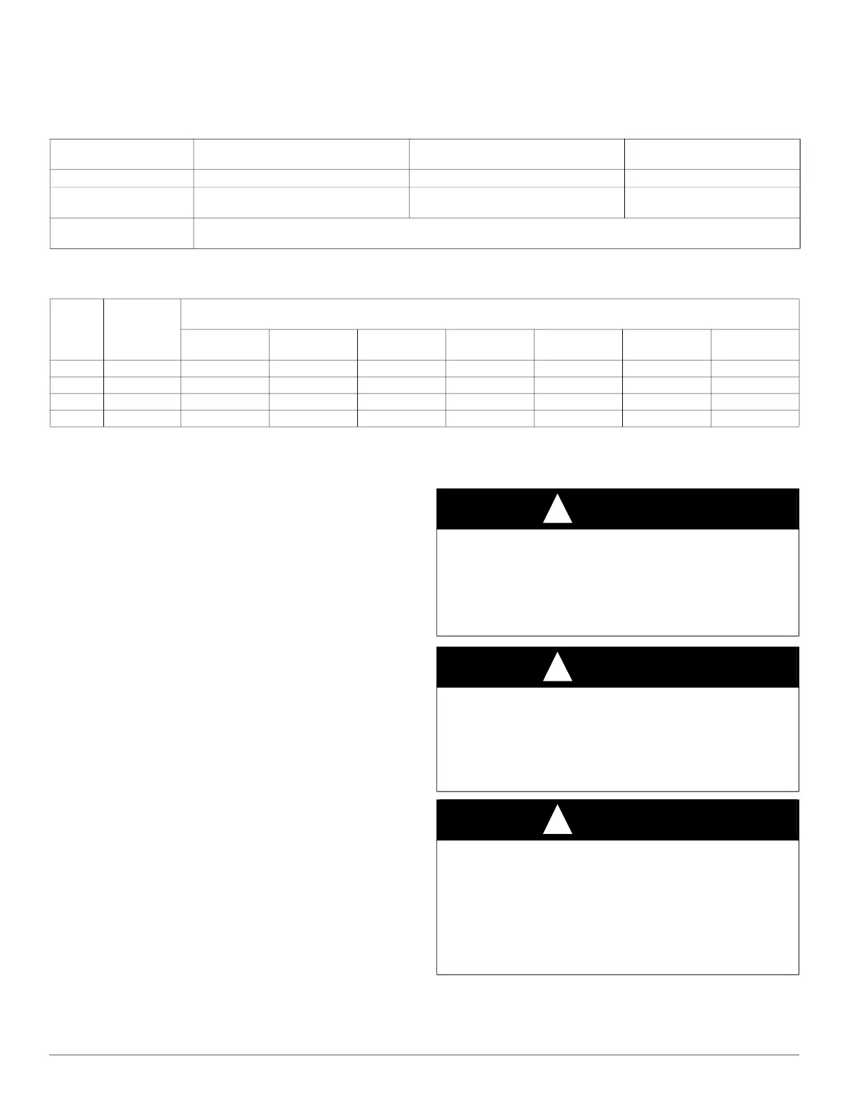
REFRIGERANT PIPING LENGTH LIMITATIONS
Maximum Line Lengths:
The maximum allowable total equivalent length varies depending on the vertical separation. See the tables below for allowable lengths depending on
whether the outdoor unit is on the same level, above or below the outdoor unit.
LONG LINE APPLICATIONS
Unit is approved for up to 100 ft (30.5 m) equivalent length and vertical
separations shown above with no additional accessories.
Longer line set applications are not permitted.
Refrigeration systems contain refrigerant under pressure. Extreme
caution should be observed when handling refrigerants. Wear safety
glasses and gloves to prevent personal injury. During normal system
operations, some components are hot and can cause burns. Rotating fan
blades can cause personal injury. Appropriate safety considerations are
posted throughout this manual where potentially dangerous techniques
are addressed.
If you do not understand any of the warnings, contact your product
distributor for better interpretation of the warnings.
GENERAL INFORMATION
The *VH8 & VA9 split system heat pump and air conditioners features
a new outdoor cabinet design that uses a four-sided coil design to
minimize the unit footprint and provide the best heat exchange taking
full advantage of the latest variable speed technology.
The heart of the system is the variable speed rotary compressor powered
through the use of the variable speed drive (VSD) inverter control.
Through the use of R-410A refrigerant, compact ECM outdoor fan
motor, VSD and variable speed rotary compressor, along with the new
outdoor cabinet, the unit achieves a Seasonal Energy Efficiency Ratio
(SEER) of up to 19 and up to 11 Heating Seasonal Performance Factor
(HSPF).
To ensure ultimate comfort, these units should be combined with either
the FCM fan coil or Variable Speed Gas furnace controlled with a two
wire communication TSTAT0201CW with version 5.0 software or
newer. This combination will ensure achievement of comfort with the
convenience of fingertip trouble shooting and diagnostic capability.
These units can also use a standard, 2-stage or single-stage thermostat,
for limited functionality.
ELECTRICAL
Table 2 – Maximum Line Lengths
MAXIMUM ACTUAL LENGTH
ft (m)
MAXIMUM EQUIVALENT LENGTH
*
ft (m)
*. Total equivalent length accounts for losses due to elbows or fitting. See the Long Line Guideline for details.
MAXIMUM VERTICAL
SEPARATION ft (m)
Units on equal level 100 (30.5) 100 (30.5)
N/A
Outdoor unit ABOVE
indoor unit
100 (30.5) 100 (30.5)
100 (30.5)
Outdoor unit BELOW
indoor unit
See Table ’Maximum Total Equivalent Length: Outdoor Unit BELOW Indoor Unit’
Table 3 – Maximum Total Equivalent Length
*
- Outdoor Unit BELOW Indoor Unit
*. Maximum actual length not to exceed 100 ft (30.5 m). Total equivalent length accounts for losses due to elbows or fittings.
-- = outside acceptable range
Size
Liquid Line
Diameter
w/ TXV
HP with R-410A Refrigerant - Maximum Total Equivalent Length{
Vertical Separation ft (m) Outdoor unit BELOW indoor unit;
0-20
(0 - 6.1)
21-30
(6.4 - 9.1)
31-40
(9.4 - 12.2)
41-50
(12.5 - 15.2)
51-60
(15.5 - 18.3)
61-70
(18.6 - 21.3)
71-80
(21.6 - 24.4)
2-Ton 3/8 100* 100* 100* 100* 100* 100* 100*
3-Ton 3/8 100* 100* 100* 100* 100* 100* 100*
4-Ton 3/8 100* 100* 100* 100* 100 100 --
5-Ton 3/8 100* 100* 100* 100* 100 100 --
WARNING
!
ELECTRICAL HAZARD - HIGH VOLTAGE!
Failure to follow this warning could result in personal injury or death.
Electrical components may hold charge. DO NOT remove control box
cover for 2 minutes after power has been removed from unit.
PRIOR TO TOUCHING ELECTRICAL COMPONENTS:
Verify zero (0) voltage at inverter connections shown on inverter cover.
WARNING
!
ELECTRICAL SHOCK HAZARD
Failure to follow this warning could result in personal injury or death.
Before installing, modifying, or servicing system, main electrical
disconnect switch must be in the OFF position. There may be more than
1 disconnect switch. Lock out and tag switch with a suitable warning
label.
WARNING
!
ELECTRICAL SHOCK HAZARD
Failure to follow this warning could result in personal injury or death.
Exercise extreme caution when working on any electrical components.
Shut off all power to system prior to troubleshooting. Some
troubleshooting techniques require power to remain on. In these
instances, exercise extreme caution to avoid danger of electrical shock.
ONLY TRAINED SERVICE PERSONNEL SHOULD PERFORM
ELECTRICAL TROUBLESHOOTING.