Do you have a question about the HWH 2000 SERIES and is the answer not in the manual?
Emphasizes reading the entire manual and securing the vehicle before any operation.
Instructs to maintain clearance and avoid contact with hydraulic fluid leaks.
Recommends safety glasses and reviewing room extension procedures.
First step for warranty is to contact the purchasing dealership for resolution.
Procedure for contacting HWH Customer Service if the dealership cannot resolve the problem.
Details pump run time limits and required cooling periods for different motor sizes.
Explains system variations and the function of the lighted reset switch for pump control.
Provides guidance for operating the system in cold weather, including oil recommendations.
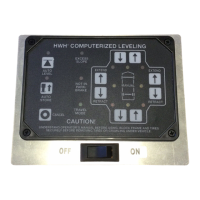
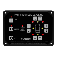
Covers vehicle clearance, parking, and control locations for leveling and room extensions.
Details checks required before travel, ensuring jacks are retracted and vehicle is secure.
Explains the purpose, activation, and troubleshooting of the lighted reset switch.
Describes the sequence for automatic vehicle leveling, including ignition and stabilization.
Details the auto store function for jack retraction and associated safety warnings.
Guidance on issues if jacks fail to retract and checking warning indicators.
Explains how to use manual valve releases to retract jacks when automatic retraction fails.
Details the process for manually retracting front and rear jacks using valve releases.
Provides instructions for extending RV rooms, including safety and lock device detachment.
Details the process for retracting RV rooms and re-engaging lock devices.
Operation of auxiliary switches for rooms, including power and safety requirements.
Guidance on operating Joey beds, including switch usage and safety.
Information on using the auxiliary pump, switch selection, and run time limitations.
Covers manual room retraction due to system failure and safe use of retract winch.
Details the steps and tools for manually retracting rooms and generator slides.
Procedure for manual retraction of the 'Universal Straight Out' room extension mechanism.
Details the steps for manually lifting the 'Universal Level Out' room extension mechanism.
Covers oil level checks, fluid types, battery maintenance, and electrical connections.
Guidance on cleaning jacks, maintenance for room extensions, and visual inspections.
Procedure to perform an operational check of the leveling system and its indicators.
Advises on cleaning jacks with soapy water to prevent corrosion from deicing agents.
Details how to adjust the sensing unit using screws and nuts to achieve proper vehicle leveling.
Procedure to check the park brake system and its indicator light functionality.
Diagram illustrating hydraulic connections for the primary pump and front/rear jacks.
Diagram showing hydraulic connections for synchronized cylinders and Joey Beds.
Diagram illustrating hydraulic connections for remote manifolds, rooms, and Joey Beds.
Diagram showing hydraulic hose and cylinder connections for room extensions and Joey Beds.
Diagram detailing hydraulic connections for the 'Universal Level Out' lifter system.
Schematic detailing wiring connections for the Central Control Module (AP35915/AP35931).
Schematic showing wiring connections for the Rear I/O Module (AP35926/AP36470).
Diagram illustrating power and control circuit connections for pump motors and relays.
Schematic detailing wiring for jack solenoids and warning/pressure switches.
Schematic showing wiring for room and Joey Bed cylinder extend/retract functions.
Schematic illustrating wiring for rear jack warning and pressure switches.
Schematic detailing wiring for Room 2/3 and Joey Bed 1/2 cylinder operations.
Diagram identifying LEDs on the Central Control Module and their descriptions.
Details pin assignments for the CN100 connector, including hydraulic switches.
Diagram showing relay functions and LED indicators for the leveling system.
Diagram detailing LED indicators and associated functions for Room 1 and Room 4.
Diagram showing LED indicators for rear jack warning and pressure switches.
Diagram detailing LED indicators and associated functions for Room 2 and Room 3.
Diagram illustrating the complete system wiring for power, control modules, and components.
Identification and manual operation for 1 1/2" and 2 1/4" cam release solenoid valves.
Identification and manual operation for 1 1/2" and 2 1/4" nut/T-handle release solenoid valves.
| Brand | HWH |
|---|---|
| Model | 2000 SERIES |
| Category | Control Systems |
| Language | English |