EasyManua.ls Logo

HWH 225 Series User Manual

HWH 225 Series
31 pages
To Next Page IconTo Next Page
Page #1 background imageLoading...
Page #1 background image
OPERATOR’S MANUAL
ML29419/MP05.2404
13FEB03
Joystick BI-AXIS Control
Hydraulic Leveling
FEATURING:
HWH CORPORATION
(On I-80, Exit 267 South)
2096 Moscow Road | Moscow, Iowa 52760
Ph: 800/321-3494 (or) 563/724-3396 | Fax: 563/724-3408
www.hwh.com
225 SERIES LEVELING SYSTEM
HWH JOYSTICK-CONTROLLED
R
Straight-Acting Jacks
AP29418
W
CORPORATION
H
H
R
RIGHT
EXTEND
HYDRAULIC LEVELING
NOT IN
ON
HWH
FRONT
EXTEND
EXTEND
BRAKE
PARK/
REAR
EXTEND
LEFT
ON
OFF
OPERATE
STORE
FRONT
5 AMP
FUSE
REAR
STORE
REMOVING TIRES OR CRAWLING UNDER VEHICLE.
BLOCK FRAME AND TIRES SECURELY BEFORE
UNDERSTAND OPERATOR’S MANUAL BEFORE USING.
CAUTION!
OPERATE
One, Two or Three Single Cylinder Room Extensions
SPACEMAKER ROOM EXTENSION SYSTEMS
AND
R
Optional Travel Clamps
R
Question and Answer IconNeed help?

Do you have a question about the HWH 225 Series and is the answer not in the manual?

HWH 225 Series Specifications

General IconGeneral
BrandHWH
Model225 Series
CategoryControl Systems
LanguageEnglish

Summary

Safety and Warranty Information

Important Safety Cautions

Essential safety warnings for operating the leveling and room extension systems.

How to Obtain Warranty Service

Procedures and contact information for claiming warranty service from HWH Corporation.

Control Panel Identification and Functions

Control Panel Components and Labels

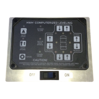
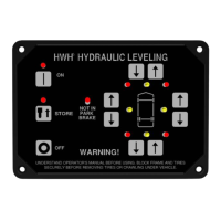
Identifies and labels all components on the HWH hydraulic leveling control panel.

Control Buttons and Indicator Lights Explained

Details the function of each button and the meaning of indicator lights on the control panel.

Room Extension Control Panel Operation

Room Operator's Panel Overview

Identifies the components of the room operator's panel for hydraulic room extensions.

Key Switch and Room Control Switch Functions

Explains how to operate the key switch and the room control switch for room extension.

Room Extension Control with Travel Clamps

Travel Clamp System Control Panel

Details the control panel for room extensions equipped with travel clamps.

Travel Clamp and Room Control Switch Functions

Explains the operation of the travel clamp and room control switches for this system.

General Operating Procedures and Leveling

General Site Selection and Instructions

Guidelines for selecting a site and general instructions before operating the system.

Leveling Procedure Steps

Step-by-step guide on how to level the vehicle using the hydraulic system.

Jacks Retraction Procedure

Jacks Retract Procedure Steps

Instructions on how to properly retract the hydraulic leveling jacks.

Important Retraction Cautions

Critical warnings regarding the retraction of leveling jacks to prevent damage.

Room Extension Operation (Without Travel Clamps)

Room Extend Procedure Steps

Detailed steps for extending a room extension without travel clamps.

Room Extend Operation Cautions

Important safety and operational cautions for extending room extensions.

Room Retraction Operation (Without Travel Clamps)

Room Retract Procedure Steps

Detailed steps for retracting a room extension without travel clamps.

Room Retract Operation Cautions

Important safety and operational cautions for retracting room extensions.

Room Extension Operation (With Travel Clamps)

Room Extend Procedure (With Travel Clamps)

Steps to extend a room extension when equipped with travel clamps.

Room Extension Interlock with Travel Clamps

Details how travel clamps affect room extension operation.

Room Retraction Operation (With Travel Clamps)

Room Retract Procedure (With Travel Clamps)

Steps to retract a room extension when equipped with travel clamps.

Room Retraction and Travel Clamp Engagement

Details how travel clamps engage upon room retraction.

Manual Room Retraction Procedure

Manual Retraction Overview and Cautions

Explains manual room retraction and critical safety warnings.

Manual Retraction Steps (Solenoid Valves)

Step-by-step guide for manual retraction using valve release nuts.

System Maintenance and Checks

Routine Maintenance Schedule and Procedures

Covers oil level, electrical system, jacks, room extensions, and visual inspection.

Operational Check Guidelines

Procedures for verifying system functionality and indicator lights.

System Checks and Adjustments

Not in Park/Brake Indicator Check

Procedure to verify the 'Not in Park/Brake' indicator light function.

Level Sensing Unit Adjustment Procedure

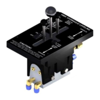
How to adjust the electronic level sensing unit for accurate leveling.

Hydraulic Diagram: 225 Series Bi-Axis Valve

225 Series Bi-Axis Valve Hydraulic Layout

Shows the hydraulic line connections for the 225 series bi-axis leveling system.

Hydraulic Diagram: Multiple Room Extensions

Multiple Room Extension Hydraulic Connections

Illustrates hydraulic line connections for systems with multiple room extensions.

Hydraulic Diagram: In-Floor Room Extensions

Dual Cylinder In-Floor Extension Connections

Shows hydraulic connections for dual cylinder in-floor room extensions.

Single Cylinder In-Floor Extension Connections

Shows hydraulic connections for single cylinder in-floor room extensions.

Hydraulic Schematic: 225 Series Bi-Axis Leveling System

225 Series Bi-Axis System Hydraulic Schematic

Detailed schematic of the hydraulic system for the 225 series joystick leveling.

Hydraulic Flow Diagram: Synchronizing Cylinder Room Extension

Vertical Arm/Dual Cylinder Flow Diagram

Illustrates hydraulic flow for vertical arm or dual cylinder room extensions with synchronizing cylinders.

Hydraulic Flow Diagram: Single Cylinder Room Extension

Single Cylinder Room Extension Flow Diagram

Illustrates hydraulic flow for single cylinder room extensions.

Electrical Diagram: 225 Series Bi-Axis Valve

225 Series Bi-Axis Valve Wiring Diagram

Shows the electrical connections for the 225 series bi-axis valve system.

Electrical Diagram: Pump Relay Connections

Pump Relay Wiring Diagram

Details the electrical connections for the leveling system's pump relay.

Electrical Diagram: Panel Connections

225 Series Panel Wiring Details

Provides specific wiring information for panel connections in the 225 series.

Electrical Diagram: Room Extension Control (with Travel Clamps)

Room Extension Control Panel Wiring

Shows the wiring for the room extension control panel with travel clamps.

Electrical Diagram: Room Extension Connection Information

Wire Functions for Room Extension Control

Detailed list of wire functions for room extension control connectors.

Electrical Diagram: Control Panel Switch Wiring

Room and Travel Clamp Switch Wiring

Details wiring for room, lock, and travel clamp switches.

Electrical Diagram: Room Extension Control Wiring

Room Extension Control System Wiring

Shows the overall wiring for the room extension control system.

Electrical Diagram: Room Extension Manifold Wiring

Room Extension Manifold Connections

Illustrates the electrical connections for the room extension manifold.

Electrical Diagram: Master Light/Buzzer

Master Warning Light and Buzzer Wiring

Details the wiring for the master warning light and buzzer system.

Breather Cap, Dipstick, and Nut Driver Information

Breather Cap and Dipstick Usage

Instructions on checking oil level using the breather cap and dipstick.

1/4" Nut Driver Functionality

Information on using the 1/4" nut driver for valve release nuts.

Related product manuals