Do you have a question about the HWH 310 SERIES and is the answer not in the manual?
Critical warnings and precautions for operating the leveling and room extension systems.
Step-by-step process for initiating and obtaining warranty repairs or service for the system.
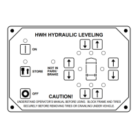
Identifies and explains the function of each button and indicator light on the HWH hydraulic leveling control panel.
Details the operation of the key switch and room control switch for the hydraulic room extension system.
Guidelines for selecting a safe site and preparing the vehicle before operating the leveling system.
Step-by-step instructions for leveling the vehicle using the touch panel control system.
Detailed steps for extending the room extension using the system's controls.
Detailed steps for retracting the room extension using the system's controls.
Instructions for retracting leveling jacks into the store/travel position using the system.
Procedures for manually retracting leveling jacks if the automatic system fails.
Explains manual room retraction when hydraulic or electric failures occur.
Details manual retraction of room/generator slides using valve release nuts.
Guidance on checking hydraulic oil levels and maintaining the electrical system for optimal performance.
Procedures for adjusting the electronic sensing unit to ensure accurate vehicle leveling.
Solutions for common issues like jacks not retracting or pump not activating.
Troubleshooting problems with leveling lights, warning lights, and master indicators.
Addresses issues where the pump activates but the room doesn't extend or retract, or creeps.
Illustrates the hydraulic line connections for dual cylinder room extensions with a synchronizing cylinder.
Depicts the hydraulic line connections for the 310 Series dual cylinder leveling system.
Provides the overall hydraulic schematic for the 305/310/325 series leveling system with straight-acting jacks.
Shows the combined electrical connections for the touch panel leveling and one room extension system.
Details the internal wiring and connections within the main control box for the leveling system.
Illustrates the specific wire connections for the touch panel interface of the leveling system.
Shows the electrical connections for the hydraulic manifold and pump relay in the 310 Series system.
Depicts the electrical connections for the single room extension system, including the operator's panel.
Presents a schematic diagram of the electrical components and flow for the room extension system.
Illustrates the wiring for the solenoid valves within the room extension hydraulic manifold.
Provides specific instructions for properly grounding the power unit and associated wiring harnesses.
Diagram showing connections for the master warning light and buzzer, integrated with the electronic sensing unit.
Instructions for checking the hydraulic oil level using the breather cap dipstick and operating the 1/4" nut driver.
| Brand | HWH |
|---|---|
| Model | 310 SERIES |
| Category | Laser Level |
| Language | English |