Do you have a question about the HWH 610 SERIES and is the answer not in the manual?
Manual is divided into three sections: Trouble Shooting, Repair Steps, and Diagrams.
Guide on how to navigate and utilize the information within the manual for effective troubleshooting.
Essential safety precautions and warnings for operating and working on the leveling system.
Pre-troubleshooting checks and important notes regarding system operation and liability.
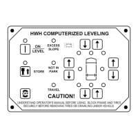
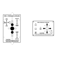
Identifies and explains the function of various buttons and indicator lights on the touch panel.
Details initial steps for checking system power, ignition status, and basic operation.
Procedures for testing the air dump function for vehicles equipped with the air dump option.
Instructions for checking the functionality and adjustment of the vehicle's sensing unit.
Steps for initiating and monitoring the automatic leveling process.
Detailed steps for retracting the leveling jacks.
Procedures for emergency manual retraction of jacks using T-handle release valves.
Instruction to refer to Section 1 for initial troubleshooting before proceeding with repairs.
Troubleshooting touch panel indicator lights with ignition off and green travel light status.
Diagnosing master jacks down light and other touch panel indicator light issues.
Troubleshooting red indicator light not on and issues with yellow indicator lights.
Diagnosing "NOT IN PARK/BRAKE" light and pump activation issues.
Troubleshooting red indicator light not flashing and low battery indicator light.
Diagnosing pump failure to start or run without effect.
Troubleshooting a jack that is vertical but its red warning light is not illuminated.
Diagnosing jacks that are vertical with foot extended or not vertical with red light off.
Troubleshooting jacks extended horizontally and retracting after pump shutdown.
Resolving issues with jacks extending but not lifting, or not retracting.
Troubleshooting air dump system not releasing air or valves not closing.
Steps for diagnosing and fixing problems with the yellow level indicator lights.
Diagnosing red indicator light and automatic air dump during leveling.
Diagnosing issues with incorrect leveling or the excess slope indicator light activating.
Troubleshooting jacks that are not providing stable support to the coach.
Resolving problems where jacks lift the coach unevenly during the stabilize mode.
Troubleshooting coach not returning to ride height and pump activation.
Diagnosing jack retraction issues and persistent red warning lights.
Resolving master dash warning light and green travel light not illuminating.
Instructions for grounding control box and 3" motor.
Guidance on pressure/warning switches and pressure switch adjustment.
When to replace control box/touch panel and actuator replacement guidance.
Proper routing and sealing of the ground wire for the control box.
Step-by-step checklist for grounding the control box, including cleaning and sealing.
Instructions for connecting the ground cable strap to the pump motor and frame.
Illustrates the side view of the ground cable connection detail.
Step-by-step grounding instructions for 6,000 pound kick-down jacks.
How to route and secure wires to allow jack movement.
Step-by-step grounding instructions for 9,000 pound kick-down jacks.
Instructions for mounting the new warning switch to the jack barrel.
Instructions for installing the new steel actuator tube and special "T" fitting.
Steps to remove the existing pressure switch and elbow.
Procedures for installing 6000# jacks and routing hoses and wires.
Detailed steps for grounding the ring terminal on the warning switch.
Instructions for routing hoses and wires for 9000# jacks, ensuring no damage.
Steps for grounding the warning switch terminal for 9000# jacks.
Procedures for routing hoses and wires for 16,000# jacks, ensuring clearance.
Steps for grounding the warning switch terminal for 16,000# jacks.
Detailed instructions on adjusting jack pressure switches for proper coach stabilization.
Differentiates between old and new style pressure switches and their adjustments.
Note regarding the operation of valve release T-handles for manual jack retraction.
Diagram showing the pump/manifold assembly, shuttle valve, and velocity valves.
Schematic of the hydraulic power unit and solenoid manifold assembly.
Diagram illustrating connections to jack actuators and cylinders.
Diagram showing electrical and line connections for air dump solenoid valves.
Illustrates how air dump valves tee into height control valve lines.
Details wire connections and terminal functions on the 610 series control box.
Information on connecting the level sensing unit and master warning light.
Overall electrical diagram showing connections for the leveling system.
Important notes on grounding connections and Packard connectors.
Wiring diagram detailing connections for the master (A) and pump (B) relays.
Note regarding the pump ground cable usage.
Wiring diagram for the solenoid connections at the manifold.
Shows connections for the pressure switch and pump.
Detailed illustration for installing the ground cable strap on Fenner Stone pumps.
Shows a side view of the grounding detail for the pump motor.
Identifies the pressure adjust body, locking nut, rubber boot, and adjustment mechanism.
Illustrates connections for jack warning and pressure switches on a 6000# jack.
Identifies the locations for horizontal and vertical stop adjustments on the jack.
Shows connections for jack warning and pressure switches on a 9000# jack.
Identifies the horizontal stop and vertical adjustments for the jack.
Illustrates connections for jack warning and pressure switches on a 16000# jack.
Identifies horizontal and vertical stop adjustments for the jack.
Critical caution regarding the purple wire in the master warning light harness and ignition status.
Shows the connection of the master warning light to the control box.
Guidelines for selecting a proper mounting surface for the level sensing unit.
Step-by-step method for adjusting the sensing unit to ensure correct leveling.
| Brand | HWH |
|---|---|
| Model | 610 SERIES |
| Category | Lifting Systems |
| Language | English |