EasyManua.ls Logo

HWH 700 Series User Manual

HWH 700 Series
39 pages
To Next Page IconTo Next Page
Page #1 background imageLoading...
Page #1 background image
C:\TEMP\ml59101.doc | Revised: 20JUN18 | Page 1 of 39
SERVICE MANUAL
FEATURING:
HWH CORPORATION
(On I-80, Exit 267 South)
2096 Moscow Road | Moscow, Iowa 52760
Ph: 800/321-3494 (or) 563/724-3396 | Fax: 563/724-3408
www.hwh.com
700 SERIES AIR LEVELING SYSTEM
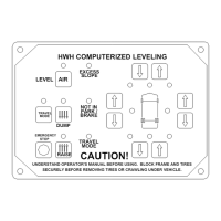
HWH COMPUTER-CONTROLLED
R
R
R
NOT IN
BRAKE
PARK /
TRAVEL
MODE
CAUTION!
SECURELY BEFORE REMOVING TIRES OR CRAWLING UNDER VEHICLE.
UNDERSTAND OPERATOR'S MANUAL BEFORE USING. BLOCK FRAME AND TIRES
DUMP
RAISE
STOP
EMERGENCY
TRAVEL
MODE
SLOPE
EXCESS
HWH COMPUTERIZED LEVELING
LEVEL
AIR

Questions and Answers:

HWH 700 Series Specifications

General IconGeneral
Input Voltage24 VDC
Output Voltage24 VDC
Operating Temperature-20°C to +60°C
Protection ClassIP20
Series700 Series

Summary

Manual Structure and Usage

Trouble Shooting Essentials

Control Panel Interface Overview

System Operation Modes Explained

Automatic Leveling Sequence

Describes the automatic leveling process, including sleep mode and excess slope.

Manual Operation and Functions

Explains manual control via arrow buttons and the dump/raise functions.

Trouble Shooting Fundamentals

Trouble Shooting - Core Diagnostics

Step 1: TRAVEL MODE and Link Light Checks

Diagnoses issues related to the TRAVEL MODE light and inter-module communication.

Step 1b Cont.: Power and Wiring Diagnostics

Step 1b Cont.: Fuse, Relay, Travel Mode Activation

Step 2: Air Bag Inflation Checks

Checks if air bags inflate correctly during system operation.

Step 2b Cont. & Step 3: Deflation and Inflation Issues

Step 4: Manual Air Bag Control and Inflation Test

Step 4b-4f: Manual Control Specific Problems

Trouble Shooting - Compressor, Level Lights, Park Brake

Step 5: Compressor Operation and Output Test

Verifies the compressor runs and builds adequate air pressure.

Step 5b Cont. & Step 6: Compressor Pressure and Level Lights

Step 6b-6c & Step 7: Level Light Errors and Park Brake Test

Trouble Shooting - Pressure Switches and Warning Lights

Step 8: 20 PSI Air Bag Pressure Switch Test

Verifies the function of the 20 PSI air bag pressure switches.

Step 9: 85 PSI System Pressure Switch Test

Step 10 & 11: Warning Lights and RAISE Button Test

Diagnoses the master warning light and the RAISE button functionality.

Automatic Leveling Diagnostics

Step 12a-12c: Automatic Leveling Sequence Issues

Addresses common issues like 'Not in Park' light, inactive leveling light, or improper leveling.

Step 12d: Leveling Active Light Behavior

Step 12e-12f: Excess Slope and Sleep Mode Problems

Diagnoses problems related to Excess Slope or Sleep mode entry.

Sensing Unit Maintenance and Adjustment

Front Air Manifold Regulator Adjustment

Air Line Connection Diagram - 4-Point System

Air Line Schematic with Pressure Switches

Air Solenoid Manifold - Front Configuration

Air Solenoid Manifold - Rear Configuration

HWH Air Compressor Connection Diagram

HWH Air Compressor System Schematic

Overall Electrical Harness Routing

Front Manifold I/O Module Wiring - Part 1

Front Manifold I/O Module Wiring - Part 2

Rear Manifold I/O Module Wiring - Part 1

Rear Manifold I/O Module Wiring - Part 2

Leveling System Latch Relays Diagram

Level Sensing Unit Electrical Diagram

Air Compressor Electrical Diagram - Part 1

Air Compressor Electrical Diagram - Part 2

Touch Panel Electrical Connections

Related product manuals