EasyManua.ls Logo

HWH 725 SERIES - User Manual

HWH 725 SERIES
27 pages
Print Icon
To Next Page IconTo Next Page
Loading...
OPERATOR’S MANUAL
ML47964/MP04.3374
19JAN11
Touch Panel Leveling Control
Single Step BI-AXIS Hydraulic Leveling
FEATURING:
HWH CORPORATION
(On I-80, Exit 267 South)
2096 Moscow Road | Moscow, Iowa 52760
Ph: 800/321-3494 (or) 563/724-3396 | Fax: 563/724-3408
www.hwh.com
725 SERIES LEVELING SYSTEM
HWH COMPUTER-CONTROLLED
R
Straight-Acting Jacks
AP47963
R
Pilot Air Dump
SPACEMAKER ROOM EXTENSION SYSTEMS
AND
R
RETRACT
EXTEND
HWH COMPUTERIZED LEVELING
SECURELY BEFORE REMOVING TIRES OR CRAWLING UNDER VEHICLE.
UNDERSTAND OPERATOR’S MANUAL BEFORE USING. BLOCK FRAME AND TIRES
STORE
AUTO
CANCEL
AUTO
LEVEL
TRAVEL
BRAKE
MODE
WARNING!
EXCESS
SLOPE
NOT IN
PARK/
R
MANUAL
RETRACT
EXTEND
CORPORATION
W
H
H
R
DUMP
MANUAL
Generator Slide

Other manuals for HWH 725 SERIES

Question and Answer IconNeed help?

Do you have a question about the HWH 725 SERIES and is the answer not in the manual?

Summary

General Safety Warnings

Control Panel and System Identification

Control Buttons and Indicator Lights

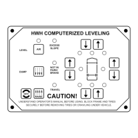
Details functions of buttons and meaning of indicator lights on the HWH control panel.

Generator Slide Control Identification

Pump Run Time and Cold Weather Operations

Pump Run Time

Information on pump motor run time limits and cooling requirements.

Cold Weather Operations

Guidelines for operating the system in cold weather conditions.

Operating Procedures - General

General Instructions

Provides general guidelines for operating the HWH leveling system and room extensions.

Preparation for Travel

Outlines steps and precautions before moving the vehicle for travel.

Automatic Hydraulic Leveling

Jack Retraction Procedures

Manual Hydraulic Operations

Manual Hydraulic Operation

Guide to manually extending and retracting jacks using the control panel.

Manual Jack Retraction

Procedure for manually retracting jacks when automatic function fails.

Generator Slide Operating Procedures

Generator Slide Extend Procedure

Steps to extend the generator slide using the control switch.

Generator Slide Retract Procedure

Steps to retract the generator slide using the control switch.

Manual Room and Generator Slide Retraction

Maintenance Procedures

Oil Level

Details how to check and maintain the hydraulic oil level.

Electrical System

Guidance on checking battery and electrical connections.

Jacks

Maintenance requirements for the jacks, including cleaning.

Room Extensions

Notes on maintenance for room extension mechanisms.

Visual Inspection

Periodic checks for leaks, damage, and interference.

Operational Check

Steps to verify system operation and indicator lights.

Additional Maintenance Checks

Not in Park;Brake Check

Procedure to verify the "Not in Park/Brake" indicator function.

Winter Weather Driving

Advice on driving and maintaining jacks in winter conditions.

Sensing Unit Maintenance and Adjustment

Sensing Unit Accuracy Tolerance

Specifies the accuracy tolerance of the leveling sensing unit.

Sensing Unit Adjustment

Provides instructions for adjusting the sensing unit for proper leveling.

Hydraulic Line Connection Diagram

Hydraulic Schematic Diagram

Generator Slide Hydraulic Line Diagram

Electrical Diagram - Leveling System

Electrical Diagram - I;O Module (Black Strike)

Electrical Diagram - I;O Module (Gray Ampseal)

Electrical Diagram - Leveling System Manifold

Electrical Diagram - Generator Slide Manifold

Electrical Diagram - Touch Panel Connections

Electrical Diagram - Generator Slide Controls

Electrical Diagram - Level Sensing Unit

Electrical Diagram - Warning Light and Buzzer

Hydraulic Solenoid Valve Information

Solenoid Valves with Cam Release

Information on solenoid valves featuring a cam release mechanism.

Solenoid Valves with 1;4 Nut Release

Details on solenoid valves using a 1/4" nut for release.

Solenoid Valves with T-Handle Release

Information regarding solenoid valves equipped with a T-handle release.

Overview

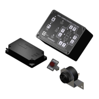
This document describes the HWH Computer-Controlled 725 Series Leveling System and Spacemaker Room Extension Systems, featuring a touch panel leveling control, single-step BI-AXIS hydraulic leveling, straight-acting jacks, pilot air dump, and generator slide.

Function Description

The HWH 725 Series Leveling System is designed to automatically or manually level a vehicle using hydraulic jacks. It also integrates with Spacemaker Room Extension Systems and a Generator Slide. The system utilizes a touch panel for control, providing indicator lights for various statuses such as auto-level, excess slope, not in park/brake, store, and travel mode. Manual buttons allow for individual control of jack extension and retraction, as well as a "manual dump" function for the vehicle's air suspension. The system is designed to stabilize the vehicle after leveling and includes safety warnings for operation.

The Generator Slide system allows for the extension and retraction of a generator slide, also controlled via a dedicated switch.

Important Technical Specifications

  • Leveling System:
    • Accuracy Tolerance: ± 5.4 inches front to rear and ± 1 inch side to side on a 36-foot vehicle.
    • Jack Type: Straight-acting hydraulic jacks.
    • Control: Computer-controlled with a touch panel interface.
    • Air Dump: Pilot air dump for vehicle suspension.
    • Pressure Switches: Includes 3000 PSI and 50 PSI pressure switches for monitoring jack status.
    • Solenoid Valves: Hydraulic manifold with solenoid valves for controlling jack extension/retraction. Some manifolds may have four large or four small valves, and some are equipped with velocity valves.
    • Hydraulic Power Unit: Features a relief valve set at 3500 P.S.I.
    • Shuttle Valve: Pressure/return shuttle valve shifts at 800 PSI.
  • Pump Motor Run Time:
    • 3" Motor: Maximum continuous run time of 4 minutes.
    • 3.7" or 4.5" Motor: Maximum continuous run time of 6 minutes.
    • Cool-down Period: 30 minutes required after maximum continuous run time to prevent motor damage.
    • Cold Weather Operation: Designed to function down to 0°F. Below freezing, jacks/rooms operate slower. For temperatures below -20°F, synthetic oil is recommended.
  • Electrical System:
    • Power: +12V ACC power from ignition switch, +12V battery power for pump and master relays.
    • Fuses: 15 AMP fuse for +12V ACC power, 40 AMP fuse for pump motor.
    • Warning System: Master "Jacks Down" warning light and buzzer, individual red warning lights for each jack.
    • Sensing Unit: Remote-mounted "potted" electronic sensing unit with yellow LEDs indicating low areas (front, left, rear, right).
    • Multiplexed Input/Output Module: Connects various system components, with LED indicators for troubleshooting.

Usage Features

  • Automatic Leveling:
    1. Place transmission in park, set parking brake, turn ignition to "ACCESSORY" (engine off).
    2. (Optional) Place pads under jacks on soft ground/asphalt.
    3. Ensure all persons and objects are clear.
    4. Press "AUTO LEVEL" button once. The system will dump air from the suspension (approx. 25 seconds) then begin leveling.
    5. The system extends appropriate jacks, turns off yellow level indicators, and then stabilizes the vehicle by checking jack pressure switches.
    6. If "EXCESS SLOPE" light comes on, the system cannot level the vehicle; retract jacks and move to a more level position or use manual leveling.
    7. Turn ignition to "OFF" after leveling.
  • Manual Hydraulic Operation:
    1. Place transmission in park, set parking brake, turn ignition to "ACCESSORY."
    2. (Optional) Place pads under jacks.
    3. Push "DUMP" button to exhaust air from suspension.
    4. Use manual EXTEND (UP ARROW) buttons to raise sides/ends of the vehicle. Level side-to-side first, then front-to-rear.
    5. Do not push EXTEND button for more than 10 seconds after jacks are fully extended.
    6. Turn ignition to "OFF" after leveling.
  • Jack Retraction (Automatic):
    1. Start engine, press "AUTO STORE" button.
    2. The store indicator light will flash. Front jacks retract for 5 seconds, then rear jacks. Red WARNING lights turn off as jacks retract.
    3. System automatically shuts down 1 minute after all red WARNING lights are out. If a light remains on, it continues for 50 minutes then shuts down.
    4. Vehicle can be moved once red warning lights are off, jacks are in STORE/TRAVEL position, and green "TRAVEL" light is on.
  • Manual Jack Retraction:
    1. Locate manual valve release on each solenoid valve (on power unit/valve assembly).
    2. Slowly open the two center valves to retract front jacks, then the two outer valves for rear jacks.
    3. Check all four jacks are retracted.
    4. Close valves by moving the valve release cam to the closed position.
  • Generator Slide Operation:
    • Extend: Set park brake, ignition to "ACC" or "ON." Press and hold "GENERATOR SLIDE CONTROL SWITCH" in "EXTEND" position. Release when fully extended. Do not hold for more than 10 seconds after full extension.
    • Retract: Set park brake, ignition to "ACC" or "ON." Press and hold "GENERATOR SLIDE CONTROL SWITCH" in "RETRACT" position. Release when fully retracted. Do not hold for more than 10 seconds after full retraction.
  • Manual Room and Generator Slide Retract (with Valve Release Nuts):
    1. Retract jacks first.
    2. Locate hydraulic pump/manifold unit.
    3. Slowly turn valve release nuts counter-clockwise (max 4.5 turns) to open solenoid valves.
    4. Locate and connect manual retract winch to the room.
    5. Slowly winch the room in by turning the winch handle clockwise.
    6. Engage room locking devices when fully retracted. Leave winch engaged and solenoid valves open.

Maintenance Features

  • Oil Level Check:
    • Check when first purchased, then every two years, or more often if there's a leak.
    • Ensure all hydraulic equipment (jacks, slide-outs, steps) are fully retracted.
    • Oil reservoir is part of the pump/manifold assembly.
    • Check and fill through the breather cap. Clear dirt before removing the cap.
    • Oil level should be within one inch of the top of the reservoir (between bottom of dipstick and center mark).
    • Fluid Type: HWH Specialty Hydraulic Oil recommended. Dexron automatic transmission fluid can be used in an emergency (contains red dye, may cause staining). DO NOT use brake fluid or hydraulic jack fluid.
    • Overfilling: Can cause leakage through the breather cap.
  • Electrical System Maintenance:
    • Ensure batteries are in good condition and fully charged. Weak batteries can cause erratic operation.
    • Keep battery cable terminals, posts, and connections clean and tight.
    • Keep all electrical connections clean, tight, free from corrosion, and protected from weathering.
  • Jacks Maintenance:
    • Require very little maintenance.
    • Wash if extremely dirty with caked-on mud.
    • Jack rods should NOT be wiped or oiled/sprayed.
  • Room Extensions Maintenance:
    • HWH room mechanisms require no maintenance.
    • DO NOT grease or lubricate any parts of the HWH mechanism.
    • Keep visible mechanisms clean by washing with water.
    • Refer to vehicle manufacturer for room seal maintenance.
  • Visual Inspection:
    • Periodically inspect for oil leaks, damaged/missing parts (pivot bolts, springs).
    • Check hydraulic lines and wiring for damage/wear.
    • Ensure jacks do not interfere with vehicle parts when in "STORE" position.
    • Keep system clean and free from caked mud or ice.
  • Operational Check:
    • Review the operator manual.
    • Run the system and note any abnormal operation.
    • Check all lights (especially red "WARNING" light) function correctly.
    • Ensure jacks fully retract to "STORE" position and do not interfere with the coach.
  • Winter Weather Driving:
    • Thoroughly wash jacks with warm soapy water after exposure to anti-icing/deicing agents to reduce corrosion.
  • Sensing Unit Adjustment:
    • Level the vehicle using a bubble level.
    • If yellow LEDs on the touch panel are lit, manually adjust the sensing unit.
    • Remove "Adjusting Enhancement Cap," apply ground to pin with jumper wire to increase sensitivity.
    • Tighten/loosen adjustment screws (1 and 3) to turn off corresponding LEDs (A/C for screw 1, B/D for screw 3).
    • Ensure mounting springs are compressed about 1/2 their free length. Screw 2 should not be turned.
    • Bump sensing unit to ensure it's settled tight and unit still indicates level.

HWH 725 SERIES Specifications

General IconGeneral
BrandHWH
Model725 SERIES
CategoryControl Panel
LanguageEnglish