49
• Attach a communications cable between Control Box and PC for set-up of the
system.
• Program the required pressure profile and other settings into the Pegasus.
o Read the current configuration.
o Make any changes required to the on-screen settings.
o Program the Pegasus with the on-screen settings.
o Re-zero pressure transducers at atmospheric pressure (not water pressure).
• Fit the mechanical actuator onto the PRV pilot. Set the range of the actuator
(required mechanical adjustment) to maximum and minimum required pressures.
• Plumb the Pegasus system into the PRV. Connect transducers.
• Activate the Pegasus to begin logging measurements and controlling the PRV.
• Test the operation of the system.
• Test communication with the central computer is OK (i.e. a call-in test).
4.1 POSITION CONTROL AND SOLENOID BOXES / LINK WITH CABLE.
The Pegasus2 Control Box and Solenoid Box can be secured to a
wall using optional brackets, shown opposite.
Ensure the wall and fixings used are able to bear the weight of
the Pegasus2 and any cables.
All cables should be routed and secured in a way that avoids
stress being put on the connectors.
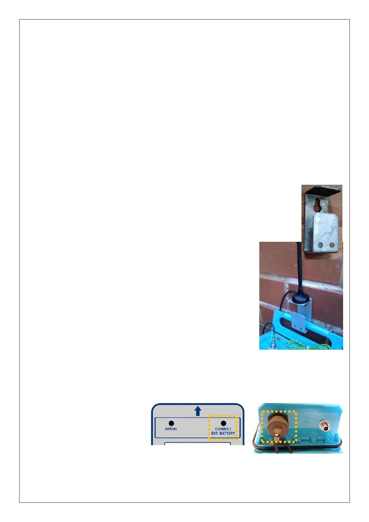
4.1.1 Antenna
The bracket offers just one potential mounting location for the
antenna, as shown.
The antenna will be connected to the connector labelled “Aerial”.
However, choice of a suitable antenna, preparation for use, and
the process of finding an optimal location for the antenna within
the installation is a topic in its own right. (See section 4.25 for
details).
4.1.2 Battery
If the system is to be installed with an external battery (optional, but sometimes
required to increase the length of service of the system), mount it in a suitable location
near the control box. It must be connected to the Control box via the connector labelled
“Comms / Ext battery”.
The external battery may be
temporarily disconnected
during parts of the installation
(whilst the Comms cable is
required to be used) but must
be re-connected at the end of
system installation.
 Loading...