50
4.1.3 Interconnection Cable
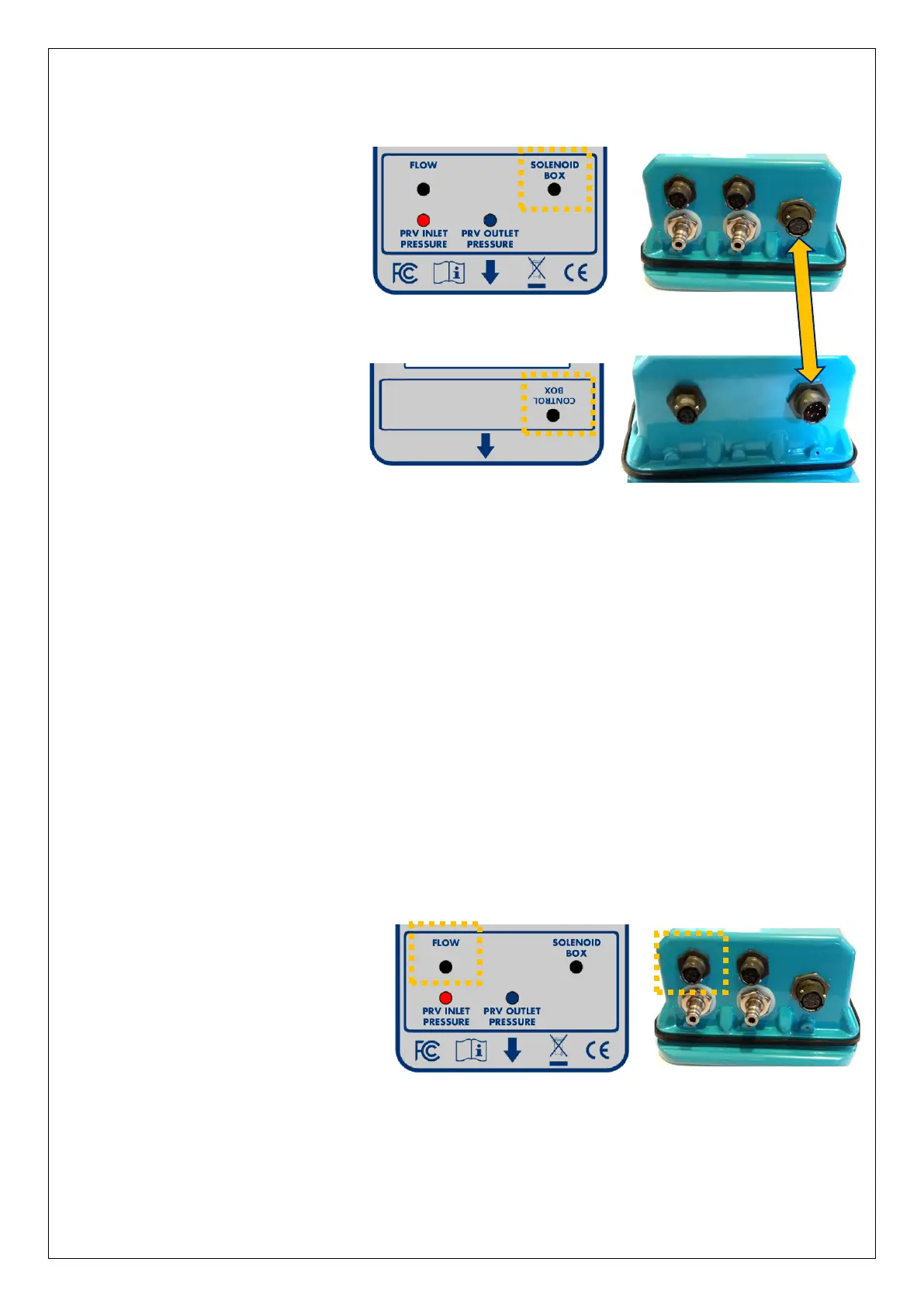
Connect the Control box to
the Solenoid box using the
6-way Pegasus2
interconnection cable
(p/n: CA-163-0004-* / length).
4.2 CONNECTION TO THE FLOW METER
Connection to the flow meter is required for any Pegasus2 that uses a pressure profile
that is dependent on flow (i.e. flow or combined time and flow).
For other situations it is optional, and will be used only by the data-logger functions.
The water flow can be detected by a flow meter near the PRV. The Flow information is
transferred to Pegasus2 by means of an electrical interface in the Control Box.
Various hardware interfaces exist for collecting flow information, including:
• Collection of meter pulses (from a contact or a volt-free pulse output).
This type of interface is suitable for supporting the PRV control functions.
(Refer to section 8.1.1 for cable diagram).
• Analogue (4-20mA) input for connection to a compatible output of a flow meter.
This type of interface is unsuitable for supporting the PRV control.
It can be used as a logger interface option only.
Connect the Flow-meter end of
the cable to the flow meter.
Then connect the cable to the
Control box via the connector
labelled “Flow”.
Note: Once the flow meter input has been set up using IDT, the flow rate can be tested
using the same screen as used for testing pressure sensors (see section 4.11).
 Loading...