• Metal towers must be grounded properly at the tower location before the tower Is erected.
This
is
to minimize electrical hazard and the possibility
of
lightning damage. Do not bury
bare aluminum
wires
or stakes in the ground. Use copper ground stakes. The service
entrance ground should be checked. The household convenience outlet should be the 3-
ron
t
e
rounded back to the service entrance
.
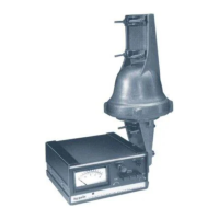
• The Control Box is not weatherproof and must be located in the house, ham shack or other
protected location.
The CD-45II Rotator has been carefully designed and manufactured to give many years of
trouble-free service when carefully and professionally installed. It consists of the strongest
and best commerciall
available com
onents.
TYPES OF INSTALLATIONS
There are three general types of installation (see Fig-
ures 4, 6, and 7).
UNBALANCED WEIGHT AND WIND
PRESSUR
1. The recommended installation is an "Inside"
Tower Mount, as shown in Figure 4, with a top
bushing or bearing to provide lateral support and
resist hi
h wind loads.
1. Unbalanced Weight: Weight should be as closely
balanced as possible. Unbalanced wight creates a
bending moment of force which is concentrated
on the mast at the point where it is clamped to
the rotator.
When the rotator is properly mounted this way, it
can be rotated to turn an antenna or beam of 8.5
square feet wind surface area. The wind loading
during storms, the rotational inertia of the beam,
and unbalanced weight are more important than
the dead weight of the beam. It is important to
minimize the height of the beam above the rotator
to minimize the overturning force induced in a
high wind ( see "Unbalanced Weight" and "Wind
Pressure"
.
2. An "Outside" Tower Mount, as per Figure 7, is the
best type of installation when not using an inside
tower mount. The rotator is not as well protected
but the installation is sim
ler.
3. A telescoping or other type mast, as shown in
Figure 6, can also be used. The lower mast
su
ort is re
uired for this installation.
There are variations of mounting, generally into one
of the above categories. For example, the rotator may
be mounted lower in the tower than shown in Figure
4. In that case, more than one bushing or thrust
bearing for the beam mast may be required and
longer coast down time allowed in operation. These
factors are interrelated and the components must be
matched together.
This moment tends to strain the mast at that
point and also to bind the ball bearings by
creating excessive downward pressure on one
side and upward pressure on the other. Such
unbalance places additional stress on the motor
and gear train. Unbalanced weight becomes
critical as the distance from the antenna boom to
the clamping point at the rotator is increased.
2. Wind Pressure: Wind pressure against the boom
and elements produces a bending force on the
mast which can cause the same stresses as
unbalanced weight. To strengthen the installation
to withstand unbalanced weight and pressure the
top mast should be as short and as strong as
possible. In multiple arrays the heaviest should be
closest to the rotator. In order to distribute the
bending stress and prevent fracture of the mast,
the CD-45-1I Rotator includes two specially
designed steel clamps to secure the mast to the
rotator.
After procuring the type of tower or other
positioning mechanism of the owner's choice, the
next step is to wire the rotator to the control box
and check out its o
eration
rior to installation.



 To Next Page