Do you have a question about the Hy-Gain HAM IV and is the answer not in the manual?
Caution regarding antenna size restrictions for mast mounting.
Safety advice for tower erection, placement, and power line proximity.
Warning about rotator mounting without a thrust bearing.
Details on mounting the rotator inside a tower with thrust bushing/bearing.
Description of optional outside tower mounting, with derated capacity.
Instructions for mounting on a mast using a lower mast support kit.
Explanation of how unbalanced weight affects mast and rotator stress.
How wind pressure impacts the mast and installation strength.
Guidance on choosing the correct wire gauge based on cable length.
Instructions for assembling the rotor cable.
Temporary attachment of screws to the bottom of the rotor unit.
Procedure for connecting and powering the control unit.
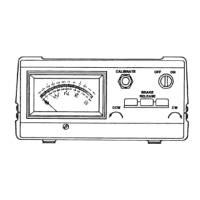
Verifying meter illumination after turning on the power switch.
Testing the brake release lever for an audible click.
Testing the rotator's CCW movement and stopping.
Testing the rotator's CW movement and stopping.
Caution on releasing direction switch to avoid stress on rotator/gears.
Locating the rotator under the bushing and cutting the tower plate for the cable.
Plugging connectors and securing the cable to prevent strain.
Trial assembly of the mast and checking maximum diameter requirements.
Tightening bolts initially and checking for concentric mast rotation.
Ensuring proper mast alignment and shimming for concentric rotation.
Checking for unrestricted 360° rotation after alignment.
Final tightening of the rotator mounting bolts to specified torque.
Tightening the bolt to prevent mast rotation in the upper support.
Caution about antenna size restriction when using the lower mast support kit.
Details on the optional kit for mast mounting the rotator.
Information on an optional kit to replace Cinch connectors with weatherproof ones.
Explanation of the thermal switch that automatically shuts off power during continuous use.
Turning on the control unit and checking meter illumination.
Operating the rotator to full CCW position for calibration.
Adjusting the meter to indicate South at the full CCW position.
Calibrating the meter by adjusting the potentiometer at full CW position.
Description of meter needle behavior when the control unit is turned off.
Retracting the brake wedge to allow rotator movement.
Turning the rotator using the direction levers.
Technique for precise positioning using nudging with large beams.
Advice against running the rotator at full speed into the limits.
Allowing the rotator to coast down before engaging the brake.
Instructions for grounding the tower or metal support device to earth ground.
Grounding the steel chassis of the control box to a metal cold water pipe or service entrance.
First step in meter scale conversion: disconnecting the power supply.
Removing and labeling the 8-wire control cable for conversion.
Instructions for removing the top and bottom covers of the control unit.
Removing the lamp and holder to access the transformer and bracket.
Removing hex nuts from meter studs to free the printed circuit board.
Caution about using a test lead to short meter studs when not in circuit.
Loosening retaining clips and removing the meter from the chassis.
Gently prying off the clear meter cover to access the scale.
Removing and reinstalling the meter scale correctly over indexing pins.
Reinstalling meter, P.C. Board, and lamp hardware, checking for issues.
Reinstalling the top and bottom covers of the control unit.
Repositioning the antenna mast if the scale was changed to South center.
Recalibrating the meter after completing the scale conversion.
Information about the separate South Centered scale provided.
Cautions regarding unit testing, wiring compatibility, and voltage.
Identifying common issues like broken/shorted wires and their impact.
Explanation of natural play in the rotator mechanism and its cause.
Addressing issues like mast slipping or turning during high winds.
Diagnosing causes for slow or hard starting, including capacitor and voltage issues.
Troubleshooting meter readings, pilot light, transformer, and fuse issues.
Performing voltage tests on control unit terminals with AC power connected.
Performing resistance tests on control unit terminals after disconnecting power.
Checking continuity of control wires for loose connections caused by wind.
Taping down the control cable securely all the way to the rotator.
Checking motor winding through the control cable as outlined in Table 2.
Checking cable for static lightning charges or direct hits causing carbon arcs.
Checking both control and rotator connectors for shorts.
Identifying causes for rotation in only one direction.
Ensuring the control cable is of proper size for the length used.
Substituting a short cable piece for bench testing to identify defective cables.
Understanding how low line voltage and cold weather affect rotation speed.
| Brand | Hy-Gain |
|---|---|
| Model | HAM IV |
| Category | Styling Iron |
| Language | English |