Pre
aration For
For OVERSEAS CUSTOMERS: If you use
the Metric System, See the American-to-
Metric conversion table in the rear of this
manual. Most illustrations in this manual will
provide both American and Metric
dimensions.
After adjustment of the tubing lengths,
tighten the clamp with a 5/16 inch nut driver,
socket, or open end wrench until the tubing
will not twist or telesco
e.
Do not overti
hten the tubin
clam
s.
Tools: The following tools are required for
eas
assembl
of the 64DX beam:
Standard wrenches or adjustable wrenches
ma
also be used in
lace of the nut drivers.
When unpacking your antenna, check inside
of all tubing for small parts and elements. To
conserve space, these smaller articles are
sometimes put inside larger pieces. Check all
parts against the parts list in the rear of this
manual to ensure no
arts are missin
.
Feedline and SWR
Model 64DX can be matched to 50 ohm coax
using the balun supplied. Without the balun,
the input impedance is 200 ohms. The SWR
can be 1.1:1 with proper installation and
necessar
care taken in assembl
.
NOTE: If resonance is affected by
environmental surroundings, shorten the
Driven Element to raise the frequency and
lengthen the Driven Element to lower the
frequency. Shorten the Driven Element in 1/4
inch increments until desired results are
obtained.
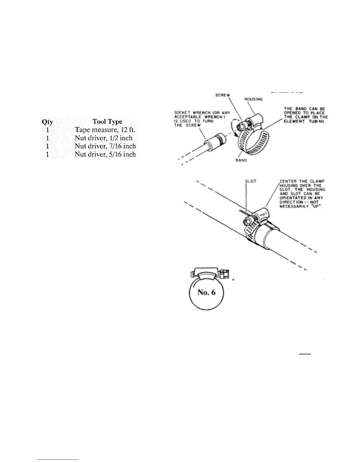
Installation of Tubin
Clam
s
Select the proper size tubing clamp as shown
in the chart in Figure l. When installing the
clamp, place the clamp near the tube end with
the top of the clamp over the slot in the tube
as shown.
Part Descri
tion Fits
No. Tubing
Sizes
358756 Clamp, Size #6 1/2
all stainless steel and 3/4"
5/16" hex head screw
Figure 1 Tubing clamp
Assembly
 Loading...