Assembl
Instructions
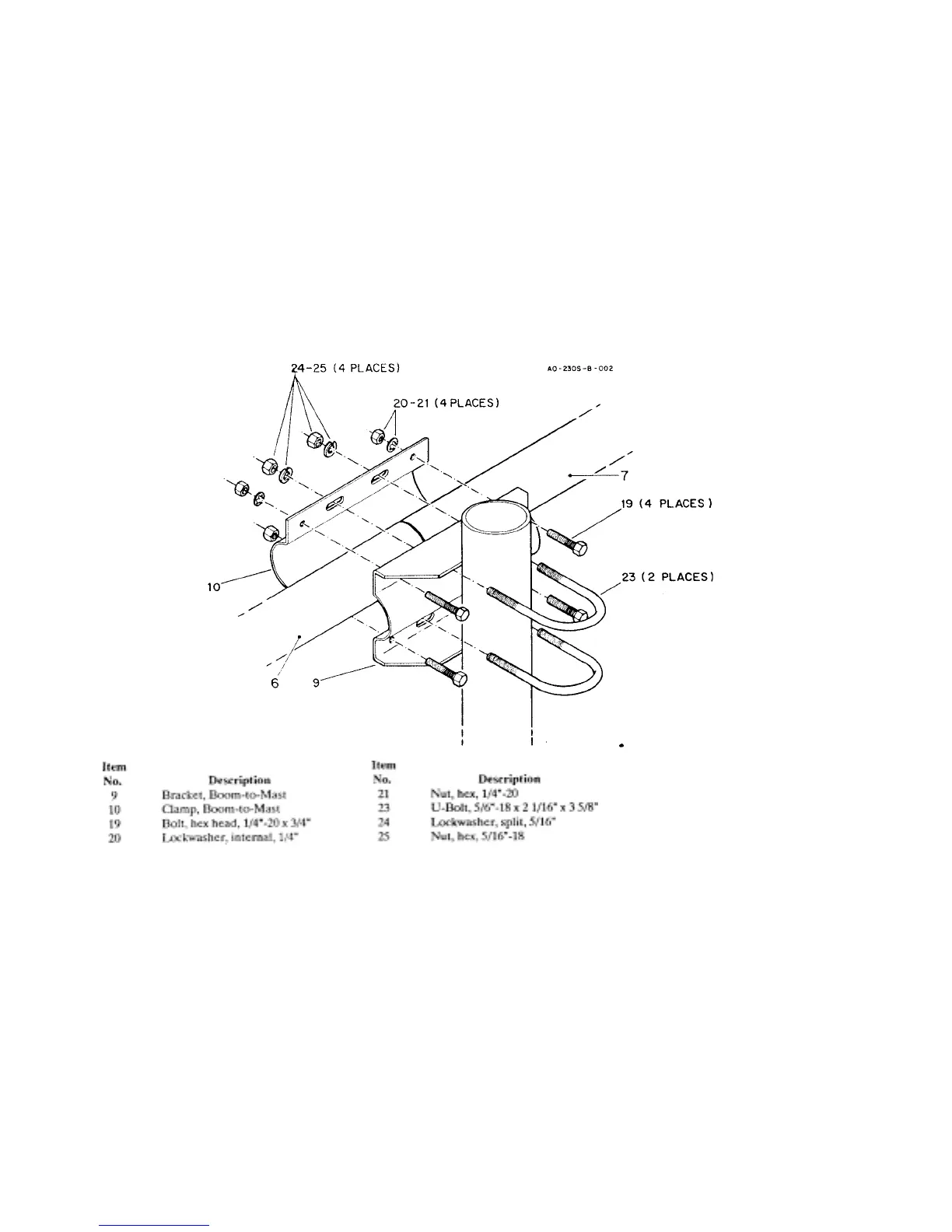
Select the boom-to-mast clamp (Item No. 10),
the boom-to-mast bracket (Item No. 9) and
four (4) 1/4" - 20 x 3/4" bolts (Item No. 19),
four (4) internal lockwashers (Item No. 20)
and four (4) 1/4" hex nuts (Item No. 21).
Place the boom-to-mast bracket body (item
No. 9) on the boom-to-mast clamp (Item No.
10), align the holes and place the bolts in the
four
4
outer holes as shown in Fi
ure 2
.
Refer to Figure 3. Select the three (3) pairs of
boom-to-element brackets (Item No. 2) and
one pair of boom-to-driven element brackets
(Item No. 1). Place a 1/4"-20x3/8" bolt (Item
No. 18) with a square nut in the large brackets
(Figure 3, Detail B) and a #10-24 x 1/2" bolt)
(Item No. 13) with a square nut in each center
hole (Figure 3, Detail A) of the small
brackets. Do Not tighten at this time. These
will now be called the anchor bolts.
Figure 2 Boom-to-
Mast Bracket
Select the two sections of boom (Item Nos. 6
& 7) and insert them into the boom-to-mast
bracket until they meet at the center. Tighten
the bolts.
NOTE: See Figure 3, Detail B. Be sure to in-
sert the bolt (Item No. 33) in the bottom half
of the bracket from the "inside-out" to attach
the beta support clamp.
Install the U-bolts and associated hardware as
shown in Fi
ure 2.
 Loading...