DETAIL A
Reflector & Director
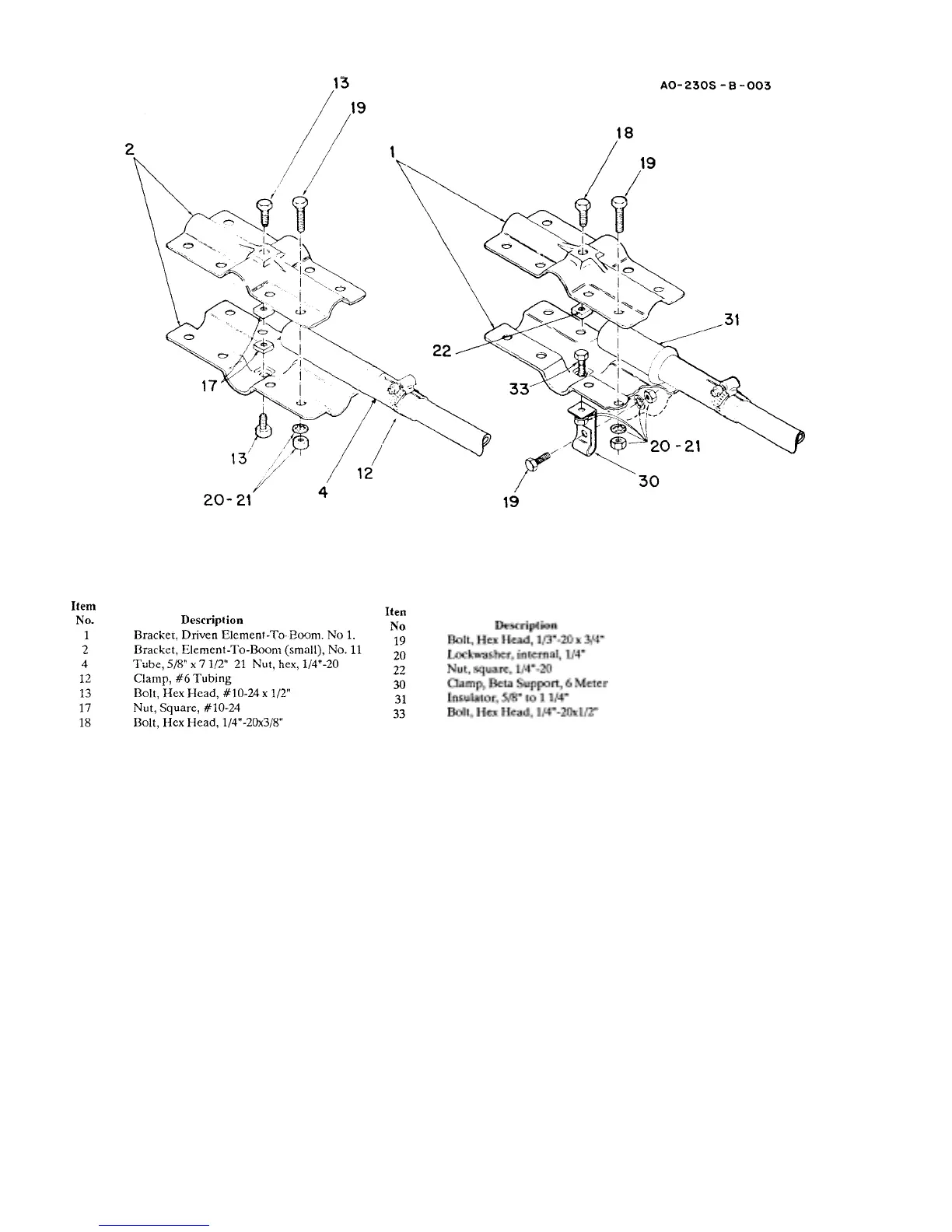
DETAIL B
Driven Element
Figure 3
Element-to-Boom Bracket
Refer to Figure 4. Place one small pair o
brackets on one end of the boom (the end that
measures approximately 68 1/4 inches from
the center of the boom-to-mast bracket). This
will be the reflector element-to-boom bracket.
Tighten the brackets loosely using 1/4"-
20x3/4" bolts (Item No. 19). Insert the 5/8"x7
1/2" tubing (Item No. 4) into each side of the
bracket and tighten all bolts securely. This
includes the center anchor bolts (Item Nos.
13, 18 & 19) on both sides of the element-to-
boom brackets.
Place a #6 tubing clamp (Item No. 12) over
the five eighths inch (5/8") tubing (Item No.
4). Insert the 7/16" x 53" tubing (Item No. 8)
into the five eighths inch (5/8") -tubing. Refer
to the chart (Figure 7) for the correct setting
and ti
hten the tubin
clam
.
Select the driven element-to-boom bracket
(Item No. 1) and install in the same manner as
described in the preceding two paragraphs.
Insert the 5/8" x 71/2" tubes (Item No. 4) into
the driven element insulators (Item No. 31).
Insert the insulators into the bracket (Item
No. 1).
 Loading...