EasyManua.ls Logo

HYDAC International RF Series - User Manual

HYDAC International RF Series
8 pages
Print Icon
To Next Page IconTo Next Page
Loading...
Filters
FIL1610-1844 / 04.19
RF Series
Service and Parts
up to 3962 gpm (15000 l/min), up to 360 psi (25 bar)
1. Maintenance
1.1 General
Please follow the maintenance instructions.
1.2 Installation
Before installing the filter into the system, check
that the operating pressure of the system does
not exceed the permitted operating pressure of
the filter.
Refer to the type code label on the filter.
1.3 Commissioning
Check that the correct filter element is installed.
Install lid, screw in cover plate bolts alternately
(except RF 30 cover plate).
1.4 Maintenance Tools
Size
Torque Value
Nm [ft-lb]
Int. hex.
Allen key
30 Hand-tight
60/110 20 [15] Hex 6.36 (1/4")
160/240 20 [15] Hex 6.36 (1/4")
330 40 [29] Hex 8 (5/16")
450/580 30 [22] Hex 8
Size
Torque Value
Nm [ft-lb]
Ext. hex.
660 150 [110] Hex 24
950/1300 200 [147] Hex 30
2500/4000 150 [110] Hex 24
5200 250 [184] Hex 30
6500/15000 250 [184] Hex 36
1.5 Torque Values
Type Max. Torque Nm[ft-lb]
VR-clog ind 30 [22]
VM-clog ind 30 [22]
Oil Drain Plug
(RF30-1300)
N/A
Oil Drain Plug-G1
(RF2500-7800)
200 [148]
Lid or end cover
Do not Torque
(See 1.3 and 2.2)
6. Replace or clean filter element(s) (only W/HC
and V elements can be cleaned).
7. Clean housing, cover plate and
contamination retainer.
8. Examine filter, especially sealing surfaces,
for mechanical damage.
9. Check O-rings – and replace if necessary
2.2 Element Installation
1. Lubricate the sealing surfaces on the filter
housing and cover plate, as well as the O-ring,
with clean operating fluid.
2. When installing a new filter element, check that
the designation corresponds to that of the old
element.
3. If present, install the contamination retainer
onto the new or cleaned filter element by
turning clockwise.
4. Place filter element(s) carefully on to the
element nozzle in the housing.
Size 450 and 580:
Push filter element onto the cover plate and
turn to secure (bayonet fitting).
Place cover plate with filter element into the
housing. In so doing, the filter element will
locate automatically in the element nozzle in
the housing.
5. Size 30:
Replace cover plate and screw in manually.
Size 60-330 and 2500-15000:
Replace cover plate and screw in cover plate
bolts by hand; then tighten bolts alternately.
Size 450 and 580:
Screw in cover plate bolts by hand; then
tighten bolts alternately.
Size 660-1300:
Replace cover plate in correct position (dowel
pin in the housing must line up with groove
in cover plate) and turn counter-clockwise
as far as it will go. Tighten cover plate bolts
alternately.
6. Switch on hydraulic system and vent filter at a
suitable point in the system.
7. Check filter for leakage.
1.6 Torque Values for Reservoir
Mounting Bolts
Size
Torque Nm
[ft-lb]
Bolt
Size
RF 30 1.5 [1.1]
M4
RF 6 0/110 5 [3.7]
M5
RF 160/240 8 [6]
M6
RF 330 20 [15]
M8
RF 660 20 [15]
M12
RF 950/1300 25 [19]
M16
2. Element Replacement
2.1 Element Removal
1. Switch off hydraulic system and release filter
pressure.
Caution: when installed inline
before opening the filter, slowly open the
vent screw and release pressure (release
pressure in the tank, if any).
2. Size 30:
Unscrew cover plate manually
Size 60-330 & 2500-15000:
Loosen cover plate bolts and lift off the cover
plate.
Size 450 and 580:
Loosen cover plate bolts. Screw two of the
bolts into the tapped extraction holes in
the cover plate, so that the cover plate is
released from its seat.
Lift off the cover plate, with the filter element
attached, from the housing.
Size 660-1300:
Unscrew cover plate bolts by approx. 2 turns
(do not need to remove completely). Turn
cover plate clockwise until it can be lifted off
by holding near the bolts (bayonet fitting).
3. Pull out filter element (with contamination
retainer, if present) by the handle.
Size 450 and 580:
Remove filter element from cover plate by
turning (bayonet fitting).
Then unscrew bolts from extraction holes in
cover plate.
4. Examine element surface for dirt residues
and larger particles since these can be an
indication of damage to components.
5. Remove contamination retainer (if present)
by turning counter-clockwise – bayonet
fitting.
NOTE:
Contamination or incomplete pressure release
on disassembly can lead to seizing of the bowl
thread.
Filter elements which cannot be cleaned
must be disposed of in accordance with
environmental protection regulations.
Question and Answer IconNeed help?

Do you have a question about the HYDAC International RF Series and is the answer not in the manual?

Overview

The HYDAC RF Series filters are designed for use in hydraulic systems, offering filtration solutions for flow rates up to 3962 gpm (15000 l/min) and operating pressures up to 360 psi (25 bar). These filters are crucial for maintaining the cleanliness of hydraulic fluids, thereby extending the lifespan of system components and ensuring optimal performance.

Function Description:

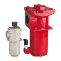
The RF Series filters are primarily used to remove contaminants from hydraulic fluids. They consist of a filter housing, a filter element, and a cover plate. Depending on the model, they can be equipped with a clogging indicator that signals when the filter element needs to be changed or cleaned. This ensures that the system operates with clean fluid, preventing wear and damage to sensitive components. The filters are available in various configurations, including different filtration ratings, element media, and bypass valve settings, to suit diverse application requirements.

Important Technical Specifications:

  • Flow Rate: Up to 3962 gpm (15000 l/min)
  • Operating Pressure: Up to 360 psi (25 bar)
  • Filtration Ratings: Available from 1 micron to 200 micron, with options like ON, ECON2, BN4AM, AM, P/HC, W/HC, and V media.
  • Seals: Nitrile rubber (NBR) as standard, with Fluorocarbon elastomer (FKM) and Ethylene propylene rubber (EPR) available as options.
  • Bypass Valves: Standard 43 psid (3 bar), with options for 14.5 psid (1 bar), 29 psid (2 bar), 87 psid (6 bar), or no bypass.
  • Clogging Indicators: Various types available, including indicator plugs, pop-up indicators (auto or manual reset), electric switches (SPDT), electric switches with LED light, visual pressure gauges, and electric switches with pop-up. Different trip pressures (29 psid/2 bar or 72 psid/5 bar) and light voltages (24V, 48V, 110V, 220V) are offered.
  • Reservoir Mounting Bolt Torque Values: Ranging from 1.5 Nm (1.1 ft-lb) for RF 30 to 25 Nm (19 ft-lb) for RF 950/1300.
  • Maintenance Tool Torque Values: Ranging from hand-tight for RF 30 to 250 Nm (184 ft-lb) for RF 5200 and RF 6500/15000.
  • Max. Torque for Clogging Indicators: 30 Nm (22 ft-lb) for VR-clog and VM-clog indicators.
  • Max. Torque for Oil Drain Plugs: N/A for RF 30-1300, and 200 Nm (148 ft-lb) for RF 2500-7800.

Usage Features:

The RF Series filters are designed for ease of installation and operation. Before installation, it is critical to verify that the system's operating pressure does not exceed the filter's permitted pressure. During commissioning, users must ensure the correct filter element is installed and the cover plate bolts are tightened alternately (except for RF 30).

For element replacement, the hydraulic system must be switched off and filter pressure released. For inline installations, the vent screw should be slowly opened to release pressure. Element removal varies by size: smaller models (RF 30) involve manual unscrewing, while larger models (RF 60-330, 2500-15000) require loosening cover plate bolts. Specific models like RF 450/580 and RF 660-1300 utilize tapped extraction holes or bayonet fittings for easier cover plate and element removal. After removal, the element surface should be inspected for dirt residues, which may indicate component damage. Contamination retainers, if present, are removed by turning counter-clockwise.

Element installation involves lubricating sealing surfaces and O-rings with clean operating fluid. New elements must match the designation of the old one. Contamination retainers are installed by turning clockwise. Elements are carefully placed onto the nozzle in the housing. For RF 450/580, the element is pushed onto the cover plate and turned to secure it before placing the assembly into the housing. Cover plate bolts are then tightened by hand and subsequently alternately to the specified torque. Finally, the hydraulic system is switched on, the filter is vented, and checked for leakage.

Maintenance Features:

Regular and careful maintenance is essential for the operational safety and extended life expectancy of the RF Series filters.

  • Element Change Interval: Recommended every 6 months or upon indication by a clogging indicator.
  • Clogging Indicators: These are vital for monitoring filter element status. If an indicator responds, the element must be changed or cleaned promptly (only W and V elements are cleanable). For systems without indicators, elements should be changed at specific intervals, which depend on filter design and operating conditions.
  • Cleanliness: Maintaining cleanliness during disassembly and reassembly is paramount. The housing, cover plate, and contamination retainer must be cleaned.
  • Inspection: All parts, especially sealing surfaces, must be inspected for mechanical damage or wear, and replaced if necessary. O-rings should be checked and replaced if needed.
  • Spare Parts: Only original HYDAC spare parts should be used to ensure technical requirements are met. Repair kits are available for various models, including O-rings for elements, cover plates, indicators, and tank seals. Contamination retainers are also available as spare parts.
  • Safety Precautions:
    • Always switch off the hydraulic system and release pressure before any work.
    • For inline filters, slowly open the vent screw to release pressure.
    • Allow pressure equipment to cool before handling.
    • Observe all statutory accident prevention regulations, safety regulations, and safety data sheets for fluids.
    • Filter housing must be grounded.
    • Avoid open flames, sparks, and smoking near hydraulic systems.
    • Ensure proper and environmentally friendly disposal of hydraulic oils and water-polluting fluids.
    • Be prepared for hot oil to escape, which can cause injury.
    • Never modify the pressure equipment (welding, drilling, etc.).
    • When using electrical clogging indicators, switch off the electrical power supply before removing the connector.

The RF Series filters are designed for incorporation into machinery and must comply with the Machinery Directive 2006/42/EC. Users are advised to consult HYDAC Technology Corporation for specific applications or operating conditions not described in the manual.

HYDAC International RF Series Specifications

General IconGeneral
BrandHYDAC International
ModelRF Series
CategoryWater Filtration Systems
LanguageEnglish