9
English
PRIME external lter
Dear Fishkeeper,
thank you for choosing this quality product. PRIME is the rst external self-priming
power lter with automatic priming chamber equipped with safety tap. Please
read the instructions carefully, you will then appreciate the lters unique features
and characteristics and you will be able to use PRIME at its best.
Description
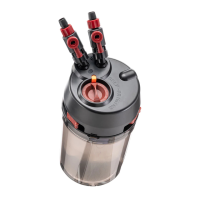
A. PUMP ASSEMBLY
A1 Sloping rotatable ttings
A2 Tap
A3 Safety locking button
A4 Clip
A5 Impeller assembly
A6 Fixed O-ring (models PRIME 20 and PRIME 30)
A7 Priming chamber
A8 Pump chamber
B. VALVE TAPS
C. FILTER UNIT
C1 Filter media container
C2 Filter body
C3 Antislip rubber feet
Installation
Attention: always disconnect all electrical equipment from the electricity supply, installed
both inside and outside your aquarium, before putting your hands in the water and be sure
that the voltage of the mains corresponds to the voltage shown on the label of the unit.
Whilst priming the lter, PRIME must be located below the aquarium level -Fig. 2-. If you
wish to place the unit at the side of the aquarium, you must do so only after priming it.
Preparing the lter
• Choose the most suitable location for the inlet and outlet systems and install them with the
locking nuts on the outside of the tank. It is suggested that the intake and outlet units should be
mounted close to the rear corners, at opposite ends -Fig. 3-.
• It is possible to adjust the height of the intake unit by inserting the extension tube between
the ow indicator and the strainer, if necessary by cutting it to the correct length. Should your
aquarium not require the extension, simply connect the strainer to the ow indicator.
• Adjust the maximum height of the outlet unit as indicated by “MAX. WATER LEVEL” and cut o any
excess tubing -Fig. 4-. Both the connector tubes must be xed to the walls of the tank by means
of the suction cups provided.
• Cut the exible tubes to the most convenient length, the cut must be at 90° to the tube wall
and as neat as possible. Connect the tubes to the inlet and outlet systems, as straight as possible
without kinks or twists, xing them with the locking nuts following the procedure as shown in
g. 5.
• For the rst 24 hours of operation it is advisable to check the closure of the connections and of
the nuts.
Fitting the valve taps
Attention: to avoid the inconvenient siphoning eect which can empty the aquarium whilst
it is being maintained, PRIME is equipped with special valve taps to ensure a perfect shut-o
of the connecting tubes. Their unique design allows their release only in the OFF position.
Screw the valves tightly on to the sloping rotatable ttings protruding from the pump
assembly -Fig. 6-. Connect the exible tubes to the valves following the same procedure
used to connect them to the collectors tubes.
Attention: connect the outlet tube with the lter exit marked “OUT” and the intake tube to
the lter inlet marked “IN” -Fig. 7-.
If the temperature is too high, after the heater has been working for 24 hours or more,
proceed as follows.
D. INTAKE UNIT
D1 Collector tube
D2 Flow indicator tube
D3 Extension tube
D4 Locking nut
D5 Strainer
E. OUTLET UNIT
E1 Collector tube
E2 Nut
E3 Multi-directional diuser
F. FLEXIBLE PIPES
 Loading...