72
120
72
120
7 - ACCESSORIES
Installation
1- Remove the hitch pin clip and the clevis pin (fi g. 7.21, p. 95) and slide one outrigger
in the top section of the bottom outrigger pockets (fi g. 7.25) on the motorized unit
or the bridge.
2- Slide the top section of a cross box (fi g. 7.26, p. 96) on the outrigger until it is
about halfway through (fi g. 7.22). Slide the top section of a second cross box on the end
of the outrigger (fi g. 7.24). Tighten the bolt on the cross boxes by hand only to hold
them in place.
4- Slide the second outrigger into the bottom section of the bottom outrigger pockets
(fi g. 7.25) and the middle section of the cross box (fi g. 7.26, p. 96) until its end is
pushed in by about 6" (15 cm) from the end of the top outrigger.
Outriggers
Doubled outriggers
(optional)
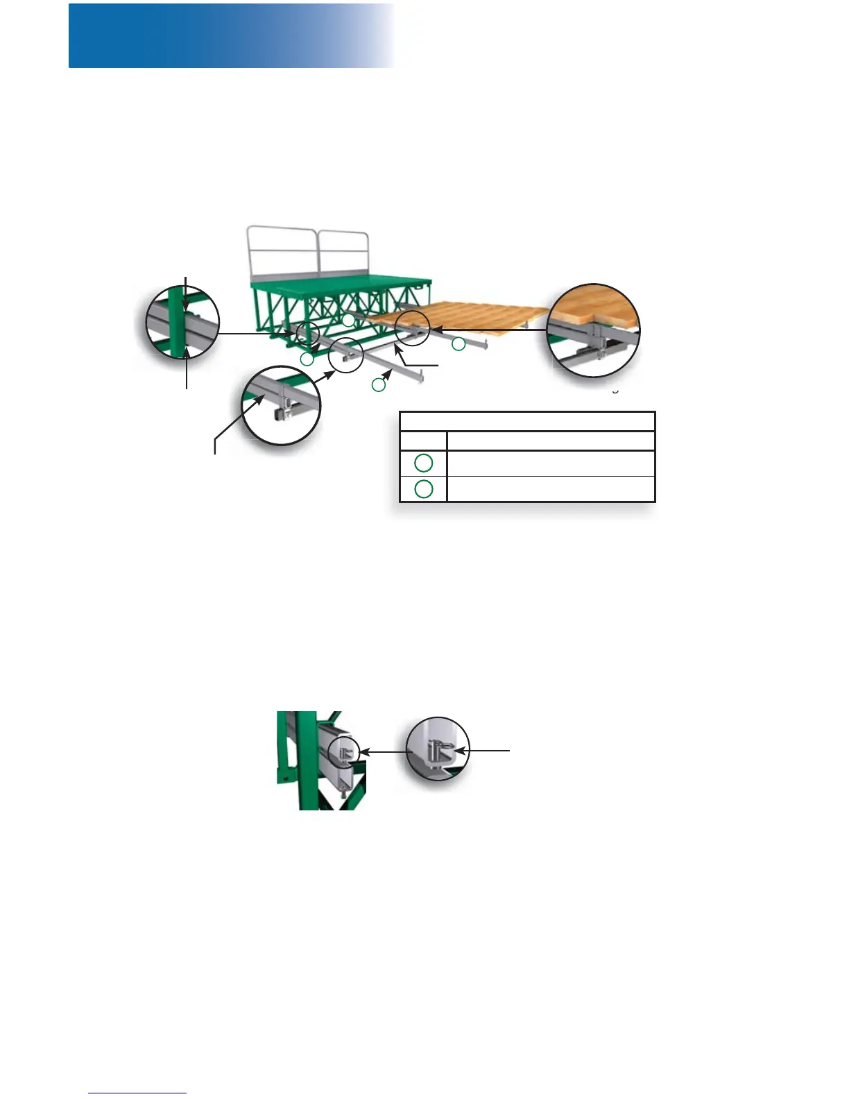
Planking confi gurations of six to eight planks wide require the use of doubled outriggers
and optional cross boxes. For more information about the installation and use of optional
cross boxes, refer to p. 97 of this section. Refer to the Outrigger Selection table (fi g. 7.19,
p. 95) for more information on the outrigger size required for each planking confi guration.
Doubled outrigger
Clevis pin must
be held up to
clear the bottom
outrigger
5- Insert the clevis pin into the top outrigger (fi g. 7.27) and pull it up until its head is snug
against the outrigger.
6- Still holding up the clevis pin on the top outrigger, pull out the bottom outrigger until
both outriggers are even (fi g. 7.28). Secure the clevis pin on the top outrigger with a
hitch pin clip. Insert a clevis pin in the bottom outrigger and secure it in place with a
hitch pin clip.
7- Tighten the bolts on all the outrigger pockets and on the top and middle sections of
the cross boxes to a torque of 30 lb-ft (41 N-m).
8- Repeat steps 1 through 7 for each doubled outrigger required.
9- Slide a cross outrigger through the bottom section of the cross boxes on the end of
the doubled outriggers (fi g. 7.22 and fi g. 7.23). Secure in place by tightening the
bottom bolt on the cross boxes to a torque of 30 lb-ft (41 N-m).
Top section of
bottom outrigger
pocket
Bottom section
of bottom
outrigger pocket
Any outrigger
according to
requirements
Outriggers Required For Doubling
Ref Outrigger
2 1/2" x 1 1/2" x 3/16" x 72"
(6,4 cm x 3,8 cm x 0,5 cm x 183 cm)
2 1/2" x 1 1/2" x 1/4" x 120"
(6,4 cm x 3,8 cm x 0,6 cm x 305 cm)
72
120


 To Next Page