22
5.5 Installation of the display deportee
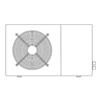
Photo(1) Photo(2) Photo(3) Photo(4) Photo(5)
- The side with plug connects with the control panel (photo1)
- The other side of the signal wire. (photo2)
- Open the wiring panel and put the side without plug through the electrical box. (photo3,4)
- Insert the wiring into the disignated position (code:COM 1 or COM-L) on the PC board. (photo5)
6. Display Controller Operation
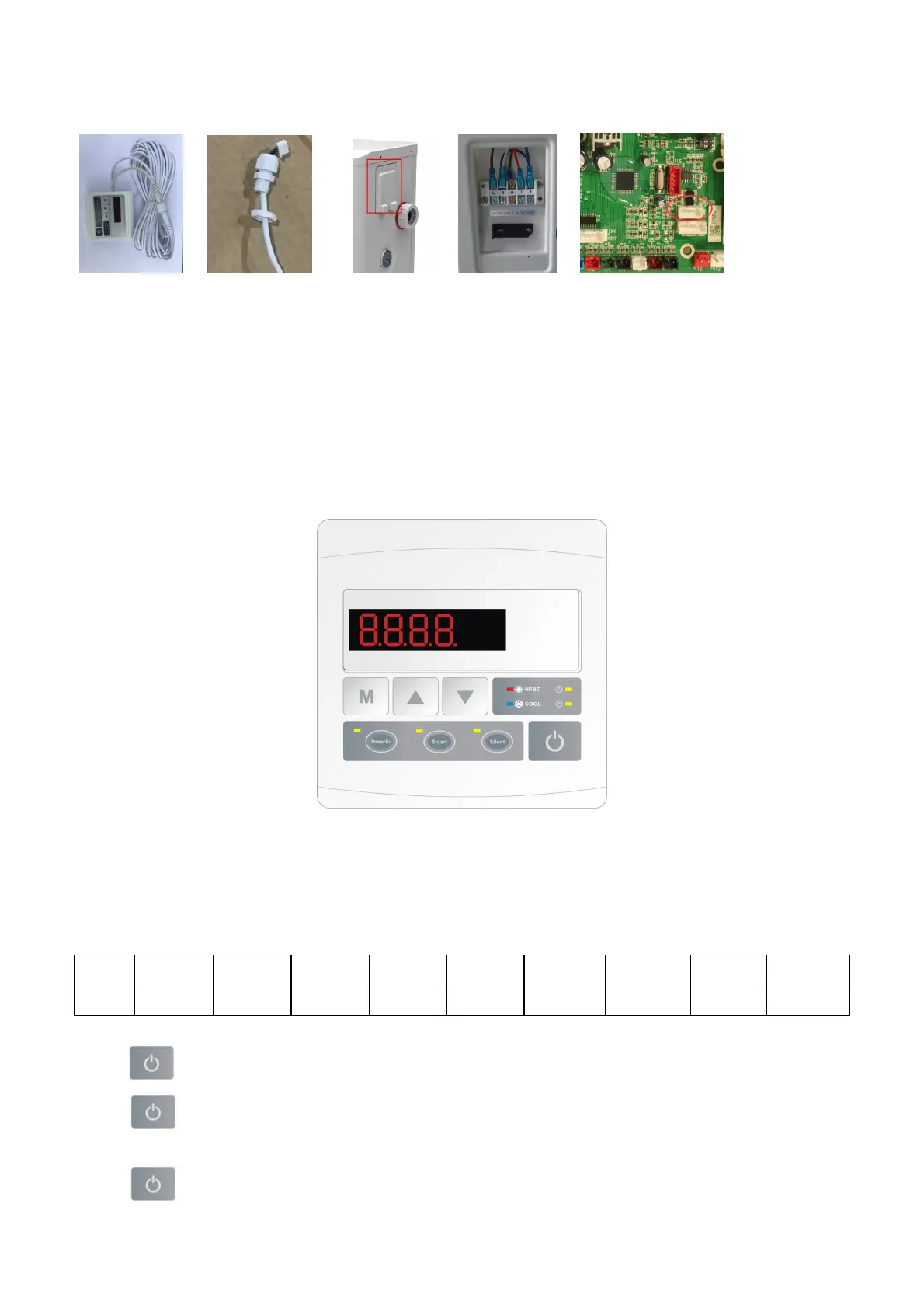
6.1 The buttons of LED wire controller
6.2 The keys and their operations
NOTE: Every time, when the heat pump connects to the power, the LED display shows a code for 3 seconds which
indicates the heat pump model.
Model
Z7/32
Z11/32 Z14/32 Z16/32
Z19/32
Z24/32
Z24T
Z29/32
Z29T
Code 1302 1304 1305 1306 1308 1311 1519 1312 1520
6.2.1 button
Press to start the heat pump unit, the LED display shows the desired water temperature for 5 seconds, then
shows the inlet water temperature and the operation mode.
Press to stop the heat pump unit and show “OFF”
 Loading...