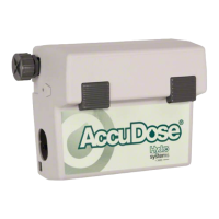
AccuDose Series Proportioner
Model 38761
with E-gap Eductors
Installation and Operation:
1. Remove cabinet cover. Drill holes for the three wall anchors with a 7mm drill bit, using the cabinet back as a template
for correct spacing of the mounting screws. Install mounting anchors, and then screws in top two anchors. Slide key
holes in cabinet back over screw heads, tighten screws, then install bottom screw. Do not mount more than1.8m
above the bottom of the concentrate container, nor below the highest concentrate level (never mount the concentrate
higher than the proportioner).
2. Select metering tips (up to 4) for the selector valve. (see next two sections) Push each tip firmly into a separate hose
barb extending from the selector valve. A tip with no hole (clear plastic) can be used to block any valve port not being
used. (This may be used for dispensing water only). Select and install a metering tip for the single product eductor
(right side) in the same manner.
3. Cut tubing provided into separate supply tubes for each product to be dispensed (tubing allows 2.1m of tube per
product). Supply tubes should reach from hose barb on the selector valve body and eductor to bottom of concentrate
container. Slide ceramic weights over one end of each tube and slide foot valves into the same ends of the tubes.
4. Slip other end of supply tube through an opening in either side of the cabinet and push over the hose barb/metering
tip on the eductor. (Repeat for all eductors.)
5. Place foot valve ends of supply tubes into concentrate containers. REMEMBER TO CHECK FOOT VALVE STRAINERS
PERIODICALLY FOR CLOGGING: CLEAN IF NECESSARY.
6. A short discharge tube is used with the 4 LPM eductor; minimum tube length is 200mm) for correct operation.
Longer tubes (1.2m) are used with a 14 LPM eductor. Do not remove the flooding rings from inside the tubes. Slide
end of tube with flooding ring over eductor discharge outlet. (Repeat for all eductors.) Hooks may be installed on longer
tubes to allow discharge tube to hang from dispenser when not in use.
7. Replace cabinet cover. Push the sides in, behind the latch holes, to snap the cover in place. The two screws provided
may be installed in the holes in the cabinet sides to prevent easy removal of cover.
8. Connect water supply hose of at least 13mm ID to water inlet swivel. (Minimum 1.76 Bar pressure, with water running,
is required for correct operation.) Connect opposite end of hose to water supply. Turn water supply on.
9. Push button to start flow of desired water/concentrate solution, and hold until supply tube is primed (filled). Then push the
button whenever dispensing is desired, and release button to stop flow of solution. If you wish to be able to lock the button
in the “on” position: clip or bend the two tabs behind the lower front portion of the button (see diagram). This allows the
button to be fully depressed and allows it to latch in the “on” position. To unlock, pull the button out.
Package Should Contain:
1. Proportioner unit.
2. Supply tubing 6.4m total.
3. Foot valve assemblies & weights (5).
4. Discharge tubing for each eductor.
5. Metering tip kits.
6. Mounting anchor kit.
7. Hose hook for 14 LPM eductor.
8. Instruction sheet.
Clip or
bend
these
tabs to
depress
button
into locked
position.