22
III. TROUBLESHOOTING
A. Installation Check – Review each of the following points fi rst.
1. Sensor Installation: Check the following points regarding the sensor installation.
a. Sensor enclosure cover must be securely fastened to protect against corrosion of the transmit-
ter board etc.
b. Sensor must be mounted at a height that is according to Figures 1a and 1b.
c. Sensor must be mounted so that (rain) water cannot come into contact with the sensor element.
Water coming into contact with the sensor element will damage the sensor and cause the need
for sensor replacement. Generally, water damage will cause the sensor to have an above zero
reading that will not return to zero.
d. Ensure that the sensor calibration cap has been removed completely. See Figure 2.
2. Monitor Installation: Check the following points regarding monitor installation.
a. Monitor should be installed at eye level in a location that is suitable for personnel to check
the sensor status before entering the chemical storage room.
b. Monitor should be mounted in a location that is protected from rain and it is recommended
that it should not be mounted under direct sunlight.
c. Monitor enclosure bolts must be securely fastened and wiring seal tights must be plugged if
not used in order to protect against corrosion of the circuit boards etc.
d. Ensure that the alarm relay output and/or 4-20mA outputs are wired according to Section II.E
and Figures 5 and 6.
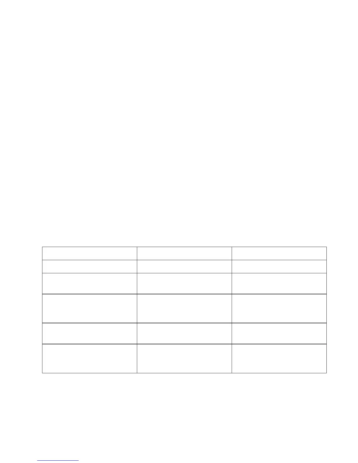
B. Symptoms, Likely Causes, and Suggested Responses
Symptoms Likely Causes Suggested Responses*
Slightly off zero in air Inaccurate zero calibration Perform zero calibration
Zero & no response with
Alarm Status: Normal
1. Calibration cap not removed
2. Wrong span calibration
1. Remove calibration cap
2. Correct span calibration
False alarm and no display
response with Alarm Status:
Error
1. Sensor disconnected
2. Sensor damaged
1. Check sensor wiring
2. Replace the sensor
High reading or reading that
won’t return to zero
Sensor damaged Replace the sensor
Blank display
1. Lost A/C power
2. Damaged circuit board
3. Damaged power supply board
1. Check A/C Power
2. Replace circuit board
3. Replace power supply board
* See Section III.C for a more detailed explanation of the suggested responses.
 Loading...