HFW-CEM-02
WIRELESS CONVENTIONAL SYSTEM
EXPANDER MODULE
Hyfire Wireless Fire Solutions Limited - Unit B12a, Holly Farm Business Park, Honiley,
Warwickshire, CV8 1NP - United Kingdom
www.hyfirewireless.com
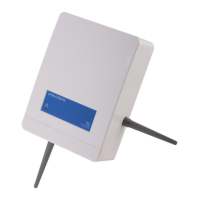
Picture 1 - Device overview
Picture 3 - Breakable holes for cable entry
Picture 2 - Wall fixing screw holes, their distances
from each other and the maximum allowed screw
diameter
Picture 6 & 7 - Power supply unit example schemes
Picture 11 - Convention-
al line wiring (zone line
EOL resistor inside of
the device)
MAIN MONITORING
BACKUP MONITORING
Picture 8 - Power
supply monitoring
lines wiring
Picture 4 - An example of a
conventional - wireless
system
DEVICE WIRING - POWER SUPPLY
The conventional system expander module must be power
supplied either:
- directly by the control panel or
- from an external power source or
- from an external power source with a power backup unit.
Use the scheme at the right for connecting the power supply to
the device.
This terminal wiring scheme is always applied.
If you want to use an external power source with a power
backup unit, two additional module’s terminal blocks come in
use: “MAIN MONITORING” and “BACKUP MONITORING”.
“MAIN MONITORING” is a terminal that supervises the main
power supply of an external power supply unit.
“BACKUP MONITORING” is a terminal that supervises the backup power supply of an external power supply unit.
Let’s have two examples of power supply units:
“MAIN MONITORING” and “BACKUP MONITORING” lines will be connected to the module as in the following scheme:
DEVICE WIRING - CONVENTIONAL ZONE LINE
In order to connect this device to the conventional zone line, two types of schemes can be used, depending on the positioning of the expand-
er module on the line:
- the expander module is positioned at the beginning or in the middle of the zone line (conventional devices follow the device on the line or
are positioned before and after it); therefore the zone line EOL resistor must be fitted externally as is normally done, but not into the device’s
terminal blocks:
- the expander module is positioned at the end of the zone line (all conventional devices are positioned before it); therefore the zone line
EOL resistor must be fitted to the device’s terminals and not externally as normally is done.
Picture 10 - Convention-
al line wiring (zone line
EOL resistor outside of
the device)
info@hyfirewireless.co.uk L20-SGCWE-1400 (vA.5)
GENERAL DESCRIPTION
The wireless conventional system expander module is a device permitting to add a wireless sub-system to a conventional fire security
installation. This device is connected directly to the conventional control panel zone line and is actually part of it. This device allows wireless
sounders silencing by being controlled by the control panel’s sounder output line.
Note: The latest release of the wireless system configuration software is available from the manufacturer’s website.
WHAT TO CHECK BEFORE INSTALLATION
Before installing the conventional system expander module
check these following items:
- This device must be installed following your national and / or international codes of practice and standards: check them befo re performing
the installation of this device.
- This device is compatible with most of the conventional control panels; check that the control panel is equipped with a power supply output
through which you can, if desired, power the conventional system expander module; check if the panel is provided with a sounder output;
check that control panel’s specifications are suitable; for all this, consult your control panel’s documentation or consult your control panel’s
supplier for more information.
DEVICE POSITIONING FOR RADIO COMMUNICATION PERFORMANCE AND STABILITY
The conventional expander module must have a good radio communication with its wireless system’s child devices. In order to achieve this,
before positioning it and installing it, apply scrupulously the following points:
- Avoid installing the module close to: · equipment using large amounts of electrical current
· large metal objects, structures or metal ceiling structures
· fluorescent lighting fixings
· computers, their cabling and network cabling.
- If there are other wireless translators or wireless modules, keep a distance between them of at least 2 meters. In general ev ery installed
radio device (child devices included) must have a minimum distance of at least 2 meters from each other.
- It is recommended to install the conventional expander at a height from the floor of at least 2 - 2.5 meters.
- Install the conventional expander perfectly flat on the wall.
- The conventional expander must be installed perfectly straight on the wall; this means that the antenna under the device must be perpen-
dicular to the floor and the antenna on the right of the device must be parallel to the floor.
Environmental parameters (temperature, humidity and so on) must be in the ranges specified in the conventional expander’s technical
specifications, which can be found at the beginning of this manual; this point applies, obviously, to all other wireless devices.
- After having installed the conventional expander, make sure that its child devices (sensors, call points, etc.) are reached by a good, strong
signal (refer to the single device’s manuals) in their position of installation.
Radio transmission ranges for the conventional expander can found in the technical specifications at the beginning of this manual.
- Use the personal computer’s “Wirelex-fire” software for configuring and administering the system.
PLACEMENT AND FIXING
The conventional system expander module’s lodgement box is designed with four 20 mm breakable, “knock-out” entry holes (two at the top
and two on the upper side of the rear of the box), allowing sealed, cable gland fitted, cables to be connected to the device.
To place and fix the module perform in sequence the following steps:
- Find a suitable location for the device’s box.
- Prepare the cable openings on the box.
- Securely and adequately fix the device’s box to the wall with adequate screws.
- Fit the cable’s gland (or glands) into the “knocked out” device box’s cable entry; check gland’s IP rating: it must be equal or greater than the
IP rating of the expander module: see the TECHNICAL SPECIFICATIONS table.
- Feed the cables into the box, giving them sufficient length for a secure connection.
WIRING CONNECTIONS
The conventional system expander module’s wiring phase of the installation has the following objectives:
- Connect the power supply cables (either from the control panel of from an independent source).
- Connect main and backup power supply monitoring inputs (optional).
- Connect the conventional zone line.
- Connect the control panel’s sounder output (optional).
- Install the end of line (EOL) resistors required as specified in this manual; their values must be chosen according to the control panel’s
specification and literature.
WIRING WARNINGS
Three warnings about wiring:
- Perform any wiring operation with the power supply source and the control panel inactive.
- Electrostatic sensitive device: observe precautions when handling and making connections.
- Connections to the terminals are polarity sensitive, thus, please, check them by referring to the wiring instructions of this manual.
IMPORTANT NOTE
Check and apply the “ZONE ALARM EOL” and the “CHECKING THE POSITIONING OF THE ELECTICAL BRIDGES“ paragraphs before
using the expander module.
928r/01
TECHNICAL SPECIFICATIONS *
Communication range between expander and
wireless devices
200 meters (in open space)
Operating frequency 868.15 MHz – 869.85 Mhz
Modulation type FSK
Operating frequency channels 7
Radiated power 5 dBm (3 mW)
Power supply voltage range **
9 VDC - 30 VDC
12 VDC typical
Power supply lower fault threshold 9 VDC
Conventional zone line applied voltage
Same as device’s power
supply applied voltage
Sounder’s line maximum voltage 27 VDC
Expander maximum current consumption 60 mA at 12 VDC (alarm)
Operating temperature range -30 °C to +50 °C
Dimensions (without antennas) 120 mm x 160 mm x 51 mm
Weight 330 grams
Ingress protection rating IP 51C
Required programming software
“Wirelex-Fire” revision 5.0
and successive
-
+
POWER SUPPLY
Picture 5 - Power
supply connection
scheme
96 mm
146 mm
4 mm
* Check latest version of document TDS-SGCWE for further data, obtainable
from your supplier.
Picture 9 - Ferrite
ring installation
WARNING!
“POWER SUPPLY -” AND “POWER SUPPLY +” WIRES MUST PASS INTO
THE SUPPLIED FERRITE RING.
IMPORTANT: Please note that with this wiring
arrangement, if a fault occurs on the wireless
sub-system, the remaining conventional zone
after the expander may be isolated until the
fault has been cleared. This will apply unless
each detector on the circuit is equipped with a
Schottky diode that the panel can use for
continuity purposes.
Please refer to your applicable codes of prac-
tice and to your conventional control panel
documentation.
* * Power source type ES1, PS2