BATTERY COVER
Detach the battery cover by pulling and lifting the closing latch.
To reinstall the battery cover, insert its two hooks into their corresponding
detector’s recesses; then block it by pressing down the opposite side, until you
hear the click of the closing latch.
INSTALLING / REMOVING THE DETECTOR
Rotate the detector clockwise on its adaptor base to install it.
Rotate the detector anti-clockwise from its adaptor base to remove it.
IDENTIFYING THE DETECTOR
The detector can be visually identified by the detachable tag imprinted with the adaptor base.
1) Detach the tag from the base.
2) Write / label the relevant identification information on the tag.
3) Insert the tag into its lodgement on the side of the adaptor base.
FIXING THE ADAPTOR BASE
Fix the base to the wall with suitable screws.
INSTALLING THE SAFETY SCREW
Always install the safety blocking screw.
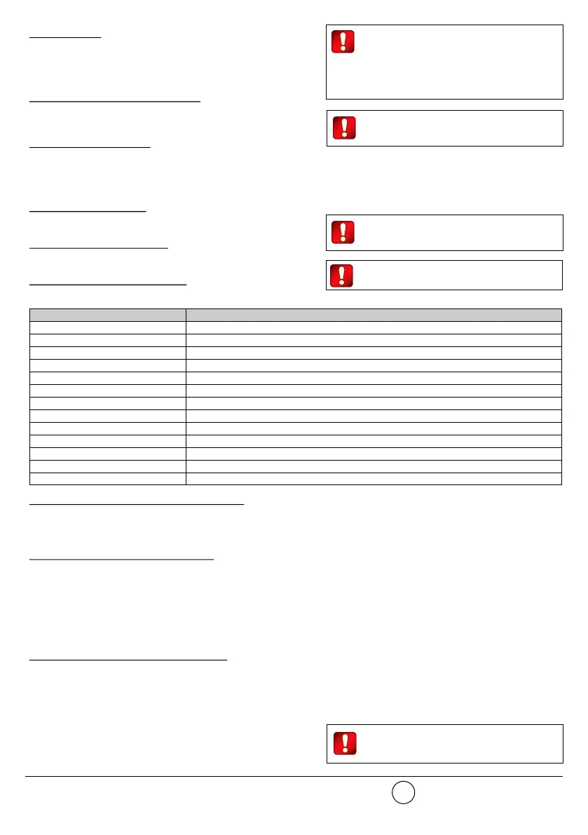
LED INDICATORS STATUS MESSAGES
The two LED indicators communicate to the final user the status of the TAU-TH-01.
POWERING UP AND LINKING - PRELIMINARY NOTES
TAU-TH-01 needs to be powered up with the supplied batteries.
Linking is the operation through which TAU-TH-01 is “wirelessly connected” to a TAU-TRM-01, TAU-CEM-01 or TAU-EXM-01 Taurus net-
work device.
LINKING - WAKE-UP - WITH INSULATING TAB
“Wake-up” linking consists in associating one or more child devices to the Taurus system altogether in a single operation.
Wake-up is performed either through the TauREX software or the TAU-TRM-01 / TAU-CEM-01 keyboard-screen interface; it CANNOT be
done through TAU-EXM-01 devices.
1) Create the “virtual model” of the TAU-TH-01 either on TauREX or on the TAU-TRM-01 / TAU-CEM-01.
2) Pull out the insulating tab.
3) Trigger the wake-up procedure either from TauREX or from the TAU-TRM-01 / TAU-CEM-01.
4) Wait the end of the “wake-up” linking procedure.
5) Check on TauREX or from TAU-TRM-01 / TAU-CEM-01 for linking success. Consult their user manual.
LINKING - ONE-BY-ONE - WITH INSULATING TAB
“One-by-one” linking consists in associating one child device at a time to the Taurus system.
This operation is performed either through the TauREX software or the TAU-TRM-01 / TAU-CEM-01 keyboard-screen interface; it CANNOT
be done through TAU-EXM-01 devices.
1) Create the “virtual model” of the TAU-TH-01 either on TauREX or on the TAU-TRM-01 / TAU-CEM-01.
2) Trigger the linking procedure either from TauREX or from the TAU-TRM-01 / TAU-CEM-01.
3) Pull out the insulating tab.
4) Wait the end of the “one-by-one” linking procedure.
5) Check on TauREX or from TAU-TRM-01 / TAU-CEM-01 for linking suc-
cess. Consult their user manual.
Always install the battery cover, since it is a vital
part of the tamper detection feature. Make sure
the battery cover is safely fixed, blocked and
closed. Make sure that the internal tamper spring fits
completely into its battery cover’s lodgement. Check,
more than once, that the cover’s external tamper switch
clicks when pressed.
When extracting the insulating tab, keep both
batteries into their lodgements with your thumb,
since they can be accidentally pulled out too.
info@hyfirewireless.co.uk L20-TWDT1-1400 (vA.4)
2
Check the alignment of the raised reference
marks on the detector and on the base.
Always install the safety blocking screw.
Table 1
Please mind that LED signalling burns out battery
power, therefore reducing batteries lifespan.
Device status LEDs indication
Power up (DIP on “ON”) Blinks red 4 times
Power up (DIP opposite “ON”) Blinks green 4 times
Entering wake-up mode Blinks alternatively green / red 4 times
Link success (one-by-one) Blinks green 4 times, then the same pattern again
Link failure (one-by-one) Enters wake-up mode and signals “Entering wake-up mode” following this failure
Link success (wake-up) Blinks green 4 times, then same pattern again
Link failure (wake-up) Blinks green 4 times, then blinks red on once, then blinks alternatively green / red 4 times
Normal condition LED off (can be programmed so as to blink green every wireless communication)
Alarm activation Blinks red every 2 seconds
Battery fault LED off (can be programmed so as to blink amber every 5 seconds)
Tamper fault LED off
Replaced Blinks amber 2 times
Test mode active Blinks green

 Loading...