EasyManua.ls Logo

hyfire Taurus Series User Manual

hyfire Taurus Series
4 pages
To Next Page IconTo Next Page
Page #1 background imageLoading...
Page #1 background image
GENERAL DESCRIPTION
The TAU-TH-01 Taurus series detector samples the environmental temperature in the protected area; when the environmental tem-
perature level or variation rate exceeds a certain degree, a fire alarm message is sent to the control panel.
TAU-TH-01 is battery powered and doesnt need any system cabling installation.
LOCATION SELECTION
Select a location for the detector that conforms to your local applicable safety standards and that is in a good position for sending / receiving
wireless signals to / from the father TAU-TRM-01, TAU-CEM-01 or TAU-EXM-01 network device.
Mount the detector as far as possible from metal objects, metal doors, metal window openings, etc. as well as cable conductors, cables
(especially from computers), otherwise the operating distance may greatly drop.
The TAU-TH-01 must NOT be installed near electronic devices and computer equipment that can interfere with its wireless communi-
cation quality.
TAU-TH-01
Hyfire Taurus Heat Detector
DEPLOYMENT PROCEDURE
1) Select a location for the detector. See LOCATION SELECTION.
2) Unbox the detector from its packaging.
3) Detach the detector from its base. See INSTALLING / REMOVING THE DETECTOR.
4) Detach the battery cover from the detector. See BATTERY COVER.
5.1) a) Link the detector to the system (insulating tab extraction).
See LINKING - WAKE-UP - WITH INSULATING TAB.
See LINKING - ONE-BY-ONE - WITH INSULATING TAB.
-- or --
5.2) a) Power up the detector.
See POWERING UP - FIRST TIME USE - WITHOUT INSULATING TAB.
See POWERING UP - RECOVERY.
b) Link the detector to the system (moving the link program switch).
See LINKING - WAKE-UP - WITHOUT INSULATING TAB.
See LINKING - ONE-BY-ONE - WITHOUT INSULATING TAB.
6) Reinstall the battery cover on the detector. See BATTERY COVER.
7) Detach the identification tag from the base adapter. See IDENTIFYING THE DETECTOR.
8) Install the base adapter. See FIXING THE ADAPTOR BASE.
9) Install the detector on the base adapter. See INSTALLING / REMOVING THE DETECTOR.
10) Install the identification tag to the base adapter, with all relevant information written / labelled on it. See IDENTIFYING THE DETECTOR.
11) Secure the detector to its base with its safety anti-tamper screw. See INSTALLING THE SAFETY SCREW.
12) Test the detector. See TESTING.
It is advisable to use the TAU-STK-01 survey kit
to locate a good wireless installation location.
Hyfire Wireless Fire Solutions Ltd - Unit B12a, Holly Farm Business Park, Honiley,
Warwickshire, CV8 1NP - United Kingdom
www.hyfirewireless.com
1) LED indicators
2) Battery A
3) Battery B
4) Link program switch
5) Tamper spring (internal)
6) Tamper switch (external)
7) Battery cover
8) Battery cover latch
9) Insulating tab
10) Wall fixing openings
11) Identification tag
12) Identification tag lodgement
13) Magnet test area
14) Base / detector reference marks
15) Safety screw
1 1
2 3
4
5
Picture 1
1
6
7
8
9
10 10
11
13
14
15
12
Question and Answer IconNeed help?

Do you have a question about the hyfire Taurus Series and is the answer not in the manual?

hyfire Taurus Series Specifications

General IconGeneral
Brandhyfire
ModelTaurus Series
CategorySecurity Sensors
LanguageEnglish

Summary

General Description and Overview

General Description

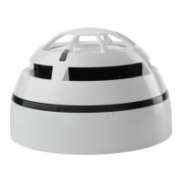
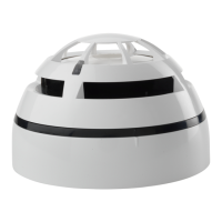
Provides an overview of the TAU-TH-01 Taurus series heat detector and its battery-powered operation.

Deployment Procedure

Outlines the step-by-step process for installing and preparing the heat detector for operation.

Location Selection

Guidance on choosing an optimal location for the detector to ensure proper wireless signal transmission.

Detector Installation and Setup

Battery Cover

Instructions for detaching and reinstalling the battery cover, emphasizing tamper detection.

Installing and Removing the Detector

Details on how to securely attach and detach the detector from its base adapter.

Identifying the Detector

Procedure for using a detachable tag to visually identify and label the detector.

Fixing the Adaptor Base

Guidance on securely mounting the detector's base adapter to a wall.

Installing the Safety Screw

Instructions for installing the anti-tamper safety screw for device security.

LED Indicators Status Messages

Explanation of LED signals indicating the detector's operational status and faults.

Powering Up and Linking Notes

Preliminary notes regarding powering the detector and the linking process to the system.

Linking Methods

Describes 'Wake-up' and 'One-by-one' linking procedures with and without an insulating tab.

Operation, Testing, and Troubleshooting

Powering Up Procedures

Covers first-time use, recovery, and powering up when linked to the system.

Linking Procedures (Without Insulating Tab)

Details 'Wake-up' and 'One-by-one' linking methods without using the insulating tab.

Testing Procedures

Guides for performing magnet and heat tests to verify detector functionality.

Battery Faults and Substitution

Procedure for addressing low battery conditions and replacing batteries.

Maintenance, Specifications, and Warranty

Maintenance and Cleaning

Instructions for cleaning the detector's thermistor area and exterior housing.

Technical Specifications

Details key technical parameters including communication range, frequency, and temperature thresholds.

Batteries Specifications

Information on the type of batteries used and their expected lifespan.

Warnings and Limitations

Important considerations for device operation, lifespan, and environmental factors.

Warranty Information

Details the limited warranty period and conditions for the TAU-TH-01 detector.

Related product manuals