Do you have a question about the HYOSUNG MONiSAFE500S and is the answer not in the manual?
Explains the manual's objective and scope for operating the MS500S system.
Identifies the intended users of the manual, including customers and staff.
Provides contact information for assistance and error resolution with the MS500S.
Outlines the manual's content, covering operation, replenishment, and jam removal.
Defines key terms used throughout the manual for clarity and understanding.
Lists and explains common abbreviations used in the document for quick reference.
Provides essential safety guidelines for handling and operating the product to prevent injury or damage.
Illustrates and explains various warning symbols and their associated safety precautions.
Lists other relevant documents, such as installation and service manuals, for further information.
Details the key hardware and software specifications of the MS500S system.
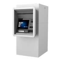
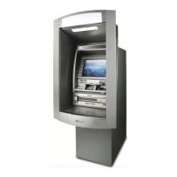
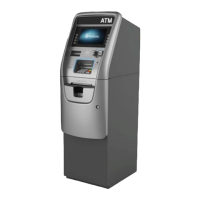
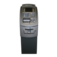
Describes the main components of the MS500S, focusing on the control electronics.
Explains how customers interact with the MS500S, including its display and input methods.
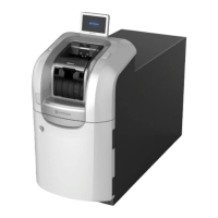
Details the functionality and specifications of the Bill Recycling Machine (BRM36).
Provides specifications and a sample picture of the TCR PNC control board.
Explains the function and specifications of the system's power supply unit.
Details the procedure for unlocking and locking the KABA 252 Vertical device.
Guides the user through the process of turning the system power on.
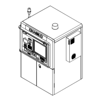
Presents a diagram illustrating the overall configuration and layout of the BRM36.
Lists the fundamental specifications and functions of the Bill Recycling Machine.
Provides detailed physical dimensions and weight specifications for the BRM36 components.
Defines the acceptable conditions for bills to be processed by the machine.
Provides step-by-step instructions for opening and closing the lower unit of the machine.
Details the steps for opening the drawer within the lower unit.
Details the steps for closing the drawer within the lower unit.
Step-by-step instructions for replenishing bills into the RJC cassette.
Details the procedure for replenishing bills into small-capacity cassettes RC11 to RC14.
Outlines the steps for replenishing bills into small-capacity cassettes RC21 to RC24.
Provides instructions on how to mount the Extra Cassette (CST).
Details the steps for safely removing the Extra Cassette (CST) from the unit.
Explains the procedure for opening and closing the upper unit of the machine.
Guides on how to open the Customer Service Module for access.
Details the steps for closing the Customer Service Module after operations.
Provides instructions for removing jammed bills from the machine.
Details how to remove a bill jam from the Customer Service Module.
Explains how to remove a jam from the front transport path of the machine.
Provides instructions for removing a jam located in the "Extra" section of the machine.
Details how to remove a jam from the Bill Checker (BC) unit.
Guides on removing a bill jam from the Option Transport Path.
Explains how to remove a jam from the middle transport path.
Details removing a jam from the lower center transport path.
Details removing a jam from the upper center transport path.
Guides on removing a jam from the upper center transport path of the lower unit.
Provides steps to remove jams from various cassette types.
| Brand | HYOSUNG |
|---|---|
| Model | MONiSAFE500S |
| Category | Cash Counter |
| Language | English |