EasyManua.ls Logo

Hyper Extension HOME GYM 50036 User Manual

Hyper Extension HOME GYM 50036
27 pages
To Next Page IconTo Next Page
Page #1 background imageLoading...
Page #1 background image
NOTE:
Please read all instructions
carefully before using this
product
Table of Contents
Safety Notice
Hardware Identifier
Assembly Instruction
Parts List
Warranty
Ordering Parts
Model
50036
Retain This
Manual for
Reference
OWNER'S
MANUAL
www.hyper-extension.com
HOME GYM
50036
Please contact HUNTER LEISURE AUSTRALIA Should any questions
arise at 1800-632-792
Warranty Service: If you require warranty service, please do not return
the gym to the store. Contact Hunter Leisure Australia on
1800-632-792.
Question and Answer IconNeed help?

Do you have a question about the Hyper Extension HOME GYM 50036 and is the answer not in the manual?

Hyper Extension HOME GYM 50036 Specifications

General IconGeneral
BrandHyper Extension
ModelHOME GYM 50036
CategoryFitness Equipment
LanguageEnglish

Summary

Before You Begin

Important Safety Notices

Precautions

Key safety guidelines for operating the exercise machine, emphasizing user health and environment.

Hardware Pack

Assembly Instructions

Step 1: Base Frame and Main Structure

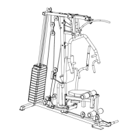
Assembling the base frames, vertical frame, seat support, and butterfly pulley bracket.

Step 2: Weight Stack Assembly

Installing guide rods, weight plates, and selector rod onto the rear base frame.

Step 3: Frame and Backrest Attachment

Attaching upper frame, backrest support, and seat support frame to the vertical frame.

Step 4: Leg Developer and Front Press Base

Attaching the leg developer to the seat support and the front press base to the upper frame.

Step 5: Front Press Mechanism

Attaching the front press mechanism to the front press base and securing positions.

Step 6: Butterfly Assembly

Attaching the butterfly base and handles to the vertical frame.

Step 7: Seat and Foam Roll Setup

Attaching the seat pad, seat post, and foam rolls to the seat support.

Step 8: Upper Cable Routing

Attaching the upper cable and pulleys, routing them to the selector rod.

Step 9: Lower Cable Routing

Attaching the lower cable and pulleys, routing to leg developer and U-shape connector.

Step 10: Butterfly Cable Routing

Attaching the butterfly cable to the butterfly pulley bracket and left butterfly.

Step 11: Accessory and Bar Connections

Connecting lat bar, abdominal strap, and shiver bar to their respective cables.

Weight Resistance Chart

Part List

Limited Warranty