6 Installation Getting Started
Please read before starting your install!
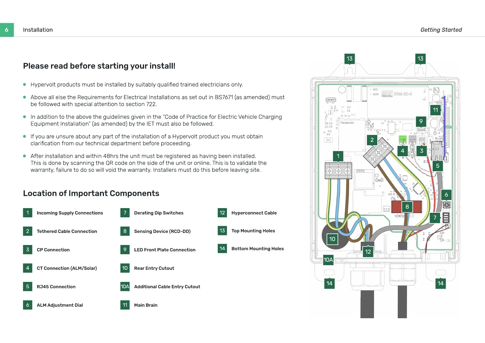
Location of Important Components
1 Incoming Supply Connections
2 Tethered Cable Connection
3 CP Connection
4 CT Connection (ALM/Solar)
5 RJ45 Connection
6 ALM Adjustment Dial
7 Derating Dip Switches
8 Sensing Device (RCD-DD)
9 LED Front Plate Connection
10 Rear Entry Cutout
10A Additional Cable Entry Cutout
11 Main Brain
12 Hyperconnect Cable
13 Top Mounting Holes
14 Bottom Mounting Holes
1
2
6
9
13 13
7
11
8
10
10A
3
12
5
14 14
4
Hypervolt products must be installed by suitably qualied trained electricians only.
A
bove all else t
h
e
R
equirements
f
or
E
lectrical
I
nstallations as set out in
BS7671
(
as amended
)
must
be
f
ollo
w
ed
w
it
h
special attention to section
722
.
I
n addition to t
h
e above t
h
e
g
uidelines
g
iven in t
h
e
“C
ode o
f
P
ractice
f
or
E
lectric
V
e
h
icle
Ch
ar
g
in
g
E
quipment
I
nstallation
”
(
as amended
)
by t
h
e
IET
must also be
f
ollo
w
ed.
If
you are unsure about any part o
f
t
h
e installation o
f
a Hypervolt product you must obtain
clarication
f
rom our tec
h
nical department be
f
ore proceedin
g
.
Af
ter installation and
w
it
h
in
48h
rs t
h
e unit must be re
g
istered as
h
avin
g
been installed.
Th
is is done by scannin
g
t
h
e
QR
code on t
h
e side o
f
t
h
e unit or online.
Th
is is to validate t
h
e
w
arranty
,
f
ailure to do so
w
ill void t
h
e
w
arranty.
I
nstallers must do t
h
is be
f
ore leavin
g
site.
 Loading...