Hypnocube 4Cube Instructions v 6.5, December 2013
- 39 -
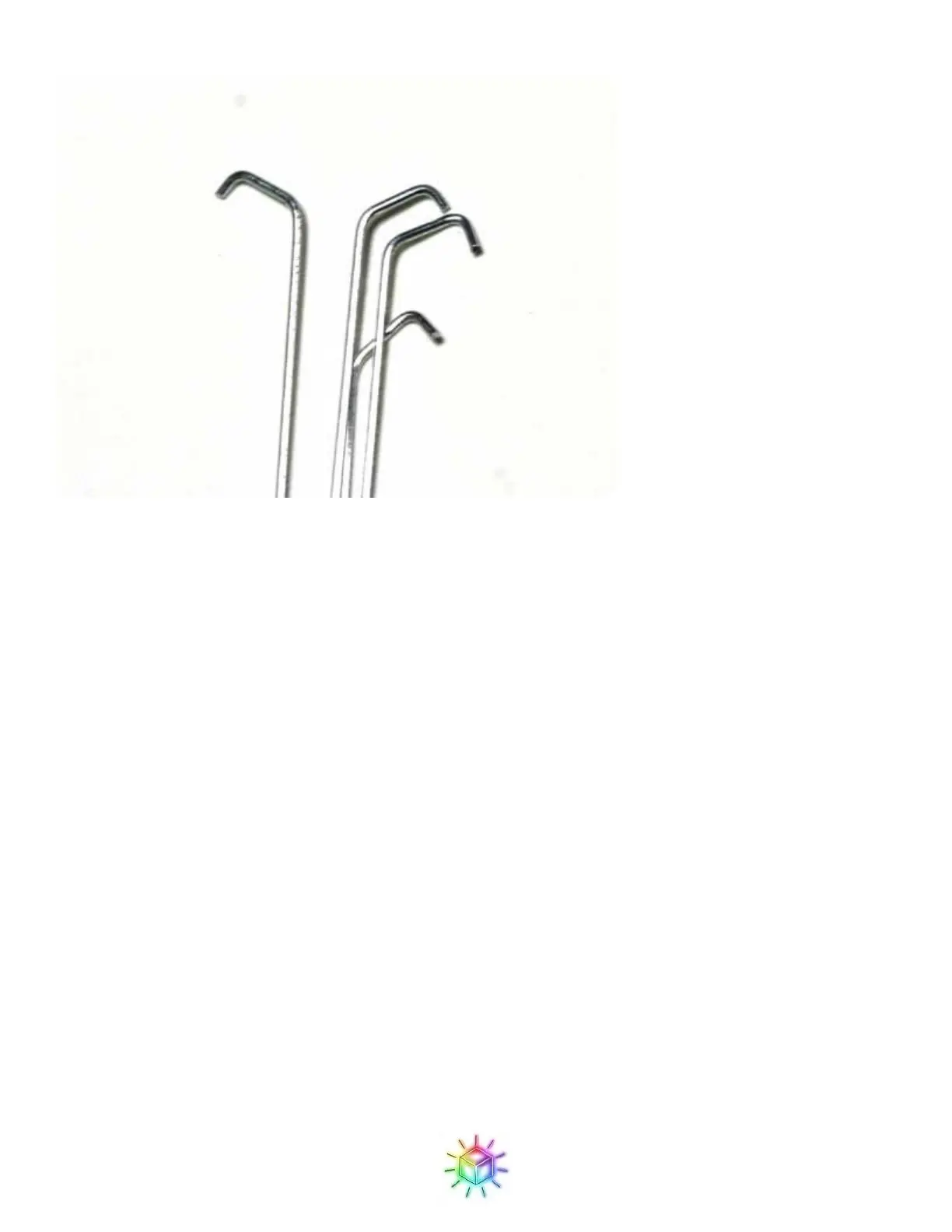
Figure 66: Close-up of hooks on the ground drop wires.
Step 4: Attaching planes
(Please note that many of the following pictures are from an older revision of the board so may look slightly
different from yours – the instructions all still apply however.)
We will add one plane at a time to the circuit board by first slotting it into the LED holes on the PCB, and then
adding the drop wires.
For the first plane, select one of the planes with the shortest wires (the ones that came from the top half of the
8x8 grid.) If you place one of the long lead planes first, you might not have enough length on later planes to
align them.
With the two planes with longer wires, you will need to trim them down to fit within the clearance provided by
the standoffs.
We will start from the back (the side with the USB jack) and work forward, as this will give us the best access
to the drop wires. The wires should align with the R, G, and B holes, as shown in Figure 67.
If the ends of the wires have any burrs, you made need to trim it slightly to get them to fit through the holes in
the PCB. A good sharp pair of cutters helps here. Also, if you happened to get any solder on the wires while
constructing the grid, you may need to clean it off.
It can be tricky getting all of the wires in the proper holes. I find it helps to approach it at an angle, so that you
start with the wires on one end and insert one at a time, rather than trying to get them to all align simultaneously
which is a recipe for madness. Make sure that all wires go straight down to the proper hole. The bottom ground
 Loading...