Do you have a question about the Hyundai HX500L and is the answer not in the manual?
| Brand | Hyundai |
|---|---|
| Model | HX500L |
| Category | Excavators |
| Language | English |
Essential safety guidelines for operating and maintaining the excavator.
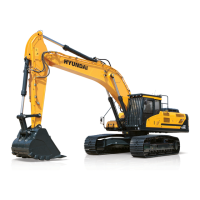
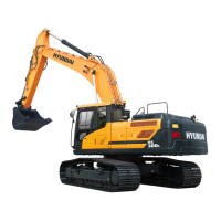
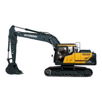
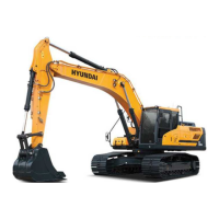
Detailed technical specifications and major component overview of the excavator.
Details on the pump device's structure and function within the hydraulic system.
Explanation of the main control valve's structure and operational function.
Description of the swing device's components and how it functions.
Information on the structure and function of the travel system.
Details on the structure and function of the receive lever.
Explanation of the receive pedal's structure and function.
Diagram and explanation of the overall hydraulic circuit.
Detailed breakdown of the main hydraulic circuit.
Explanation of the pilot hydraulic circuit and its operation.
Description of single hydraulic operations and their functions.
Details on how combined hydraulic operations work.
Identifies the location of key electrical system components.
Diagrams and explanations of the electrical circuits.
Specifications for various electrical components.
Information on electrical connectors used in the system.
An overview of the mechatronics system.
Explanation of the mode selection system's functionality.
Details on the automatic deceleration system.
Information on the power boost system.
Explanation of the travel speed control system.
Details on the automatic warming up system.
Information on the engine overheat prevention system.
Explanation of the variable power control system.
Details on the attachment flow control system.
Information on the intelligent power control system.
Preliminary steps and considerations before troubleshooting.
Troubleshooting for hydraulic and mechanical issues.
Troubleshooting guide for electrical system problems.
Troubleshooting for mechatronics system issues.
Troubleshooting for the air conditioner and heater systems.
Procedures and standards for operational performance testing.
Maintenance standards for major machine components.
Maintenance standards for track and work equipment.
Important safety precautions before disassembly/assembly.
Specifications for tightening torque for various fasteners.
Disassembly and assembly procedures for the pump device.
Procedures for disassembling and assembling the main control valve.
Step-by-step guide for swing device disassembly and assembly.
Disassembly and assembly procedures for the travel device.
Procedures for disassembling and assembling the receive lever.
Disassembly and assembly of the turning joint.
Procedures for disassembling boom, arm, and bucket cylinders.
Disassembly and assembly of the undercarriage components.
Procedures for disassembling and assembling work equipment.