Make
sure
that
the
leads
of
.the
plugs
are
in
good
condition
that
is
without
abrasions,
cracks
or
peeling;
as
this
wou.ld
impiiritre
insuiitiSn-ino
represent.a.danger
to
the
0perat'r.
D0
not
hesitate
to
replace
a lead
it
if
il-n;t-in
;;;d"worxrng
condition.
To
introduce
the reads
easiry
into.
the
sockets
in
the under
part
of the
box,
wind
the
wires
around
the
reads
or
wind
ihe
wires
themseive;
;r;
]i;
them
with
an
erastic
band.
see
sketches
A
and B
page
64.
The
high-siabiritv
current
rectifiers.
used
on this
patented
SUPERTESTER
Mod.
6g0R
are
made
of
Germanium
and
protected
ac;init;;;id;;ta'i
overloads,
even
1000
times
the
chosen
range,
The
many
th0usands
of
supERTEsrERS
6g0
arready
sord
have..
clearry
shown
the
good
realiabititv
of
the
device
itserf
and
or
hJipeciii
siiticat proieciion-*.'
t*e'iiit#ieo
uno
applied
to
our
last
type
0f
analyser
None
of
our
SUPERTESTER
680
has.been
returned
with
its
rectifiers
out
of use
or
indicating
device
damased
or
with
its
inoex
beiri
owing
i.
id.iu.i,trr
overroads
(arso
1000
times
the
chosen
range).
CHANGING
THE
BATTERY
The
battery
(ordinarv
3 Vnlt.torch.
type)
should
be
replaced
rlhen
it
is
n0 l0nger
possible
to
shift
the
pointer
io
the
fun
sc;re';aii,;;;;;;h.;"ih;
potunili:r.t.i"r,rs
nLeriioripretery
turned
to
the rieht.
rn any.
case
reptace
it-
n'i
ier.
'ihan
on.e
a
year
because
with
the
formation
of
surphates
it
might.give
iiuiium'ei
11ri
Jo,iru
damage
and
corrode
the
circuits
and the
resistances
inside
the
tEster.
io
ctlnge-irrJ"[attery
it
is
remove
the
base
plate
of
the
tester
bv roosenine
the
four
bott.m
;;;;fi;
#i
ir,,.n
r'emove
the
teti
ipiing--piessine
down
on the
b.tt'm
of
the
batterv
and
ih;;;;ir;i-ttre
nattery
which
is
now
tleir
in its
seat
when
replacins
the
batteryi-
matre
suie-lirat'ttre'potes
are in
the
correct
position
bearins
in mind
that-the
bottom
'of
itie-ratt.iv'i.'ttr'"n.guiiru-p-,,r,i
'r_i
,i"ai'iii
iop
t.
positive
pole
(1).
The
search
tor
anv
ev.irt,ialiv
iiinig..i pirt'wiil'uJ
iilatrv"ai'dea nv
consulting
the
general
schematic
circuif
and"t-ire
iiri,liii.o
detailed
circuits-in
this
manual.
38
lrr
rrrrlcr
not to dull
the surface
of the Crystal Panel,
or other
parts
in
plastic,
do
not
drop
.rrry:;older
and especially
do not
let the hot
point
of
the
soldering
iron come into contact
vrlh lhcm.
lo
rlplace
eventually
damaged
resistances
use
a
clean small soldering
iron in 0rder
not t0
rvr:rlrcat
the
printed
circuit during
the replscement
and to
avaid
damage
during the replacement
oplration.
lrr
dr:tcct
and
locate exactly
the resistance
to
lri,
rcplaced it will
be
enough
to'
look at the
l,rrrrlcd
circuit
and eventually t0 c0mpare
vJith
llrr,schematic
structural
dlagram
shown in full
'ttt: ol
page
72.
Irr
cxtract
and
substitute
the faulty component
rlnrove
the
printed
circuit as indicated
in the
lrJllrre on
page
40.
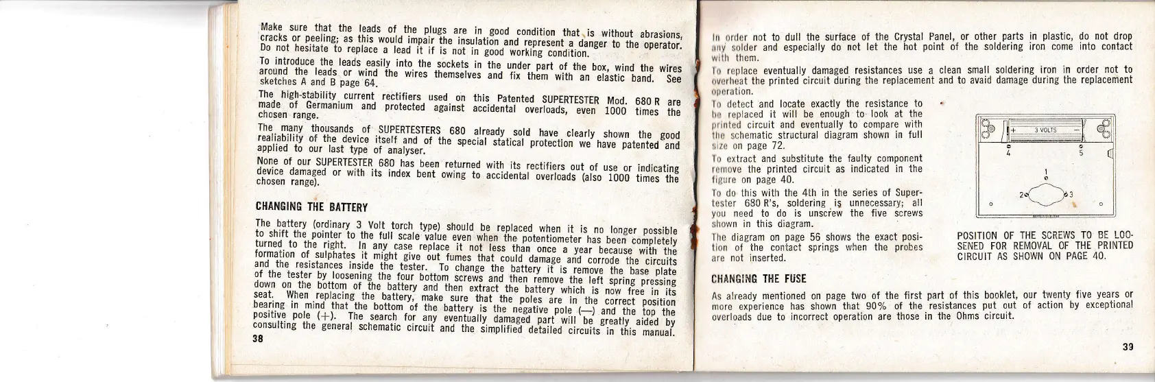
lo
do this with the
4th in the series of
Super-
lr:sler
68C
R's, soldering ig
unnecessary; all
you
need
t0 do
is unsciew the five screv;s
:,lr,rwn in this oiagram.
lhc
diagram on
page
56 shows
the exact
posi-
lion of the c0niact springs
when the
probes
irrc
not
inserted.
CHANffING THE FUSE
POSITICN
OF THE SCREWS
TO BE LOO.
SEN'ED
FOR REI'iIOVAL
CF
THE PRINTED
CIRCUIT
AS
SHOWN
ON PAGE
40.
As already mentioned on
page
two of the first
part
of
this booklet,
our
ttrenty five
years
or
nrore exp-erience has shown-that
90% of
the'resistances
put
out
of action
by exceptional
overloads due to incorrect
operation are
those in the
0hms circuit.
l
s
_/
-\
2rr
|z
ov
3g
 Loading...