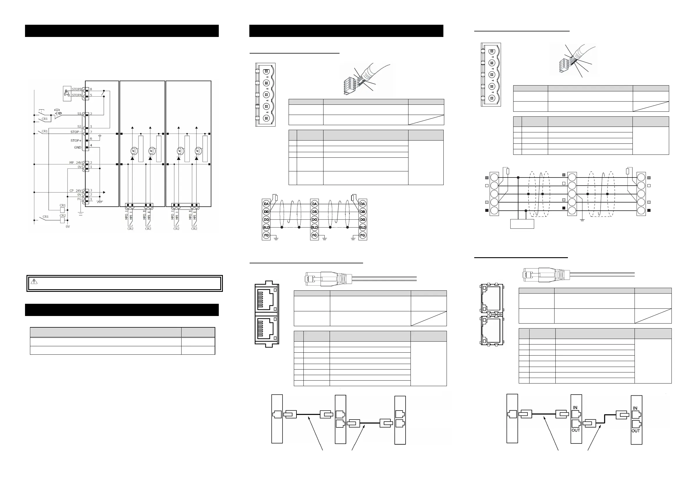
Power Supply and Stop Circuit (Example)
In the diagram below shows a circuit related to RCON drive source cutoff. For RCON, motor power is
supplied from the gateway unit, but the circuit related to the drive-source cutoff is on the driver unit side.
• Each driver unit possesses an interface (Drive source cutoff connector: MPI/MPO) available for external
drive source cutoff prepared for each axis.
• Each driver unit possesses a drive source cutoff circuit by semiconductor prepared for each axis. The
motor power should be cut off by STOP Signal. The drive source cutoff circuit by semiconductor
possesses features to detect the overcurrent and to limit the in-rush current.
Note 1 RCON-GW : If nothing is connected to the SIO connector, S1 and S2 will be short-circuited in the controller.
RCON-GWG : If nothing is connected to the SIO connector, S1 and S2 will not be short-circuited in the controller.
To short-circuit, connect the supplied dummy plug DP-5 to the SIO connector.
Note ● When externally shutting off the motor drive source to comply with the safety category or the like, connect a contact
such as a relay to the wiring between the MPI* and MPO* terminals.
● The rating of the STOP-signal to be turned ON/OFF with the contact CR1 is 24 VDC / 10 mA or less.
● The CR1 coil current must be 0.1 A or less.
● When supplying power by turning ON/OFF 24 VDC, leave 0 V connected and supply/cut off +24 V.
Warning : Note that the teaching pendant cannot have a stop for the system side even though it can have a stop for
all the actuators connected to RCON unit.
Current Amperage
For current amperage, refer to the first step guide for RCON driver unit..
Item
Document
Control
RCON 24V Driver Unit, Fan Unit, Simple Absolute Unit and Extension Unit First Step Guide ME0383
RCON 200V Power Supply Unit, Driver Unit, Fan Unit, Terminal Unit First Step Guide ME0397
Field Network Wirings and Settings
The field network connector is allocated on the top of the gateway unit. Refer to “Names for Each Part”.
1. CC-Link (RCON-GW/GWG-CC)
Refer to the instruction manuals for each field network master unit and mounted PLC for the details.
Connector Name CC-Link Connector Remarks
Cable Side MSTB2.5/5-STF-5.08 AU
(Manufactured by PHOENIX CONTACT)
Enclosed in
standard package
Controller Side MSTB2.5/5-GF-5.08 AU
(Manufactured by PHOENIX CONTACT)
Pin
No.
Signal Name
(Color)
Description
Applicable cable
diamete
1 DA (BL) Communication Line
Dedicated cable
for CC-Link
2
DB (WT) Communication Line B
3 DG (YW) Digital Ground
4
SLD Connect the shield of the shielded cable
(Connected inside to 5-pin FG and control power
suppl
connector 1-pin FG
5
FG Frame Ground
(Connected inside to 4-pin SLD and control power
suppl
connector 1-pin FG
2. CC-Link IE Field (RCON-GW/GWG-CIE)
Refer to the instruction manuals for each field network master unit and mounted PLC for the details.
Connector Name CC-Link IE Field Connector Remarks
Cable Side
Ethernet ANSI/TIA/EIA-568-B Category 5e
and above 8P8C modular plug equipped
with shield (RJ45)
Please prepare
separately
Controller Side
Ethernet ANSI/TIA/EIA-568-B Category 5e
and above 8P8C modular Jack equipped
with shield (RJ45)
Pin
No.
Signal Name Description
Applicable cable
diamete
1 TP0+ Data 0+
It is recommended
to prepare a
straight STP cable
in Category 5e or
above for the
Ethernet cable.
2 TP0- Data 0-
3 TP1+ Data 1+
4 TP2+ Data 2+
5 TP2- Data 2-
6 TP1- Data 1-
7 TP3+ Data 3+
8 TP3- Data 3-
3. DeviceNet (RCON-GW/GWG-DV)
Refer to the instruction manuals for each field network master unit and mounted PLC for the details.
Connector Name DeviceNet Connector Remarks
Cable Side MSTB2.5/5-STF-5.08 AU M
(Manufactured by PHOENIX CONTACT)
Enclosed in
standard package
Controller Side MSTB2.5/5-GF-5.08 AU
(Manufactured by PHOENIX CONTACT)
Pin
No.
Signal Name
(Color)
Description
Applicable cable
diameter
1 V- (BK) Power Supply Cable Negative Side
Dedicated cable
for DeviceNet
2 CAN L (BL) Communication Data Low Side
3 - Digital Ground
4 CAN H (WT) Communication Data High Side
5 V+ (RD) Power Supply Cable Positive Side
4. EtherCAT (RCON-GW/GWG-EC)
Refer to the instruction manuals for each field network master unit and mounted PLC for the details.
Connector Name EtherCAT Connecto
Remarks
Cable Side
Ethernet ANSI/TIA/EIA-568-B Category 5
and above 8P8C modular plug equipped
with shield (RJ45)
Please prepare
separately
Controller Side
Ethernet ANSI/TIA/EIA-568-B Category 5
and above 8P8C modular Jack equipped
with shield (RJ45)
Pin
No.
Signal Name Description
Applicable cable
diameter
1 TD+ Data sending+
It is recommended
to prepare a
straight STP cable
in Category 5 or
above for the
Ethernet cable.
2 TD- Data sending-
3 RD+ Data receiving+
4 - Disconnected
5 - Disconnected
6 RD- Data receiving-
7 - Disconnected
8 - Disconnected
Top View of
Connector on
Controller side
L.ER
LINK
L.ER
LINK
5
4
3
2
1
Top View of
Connector on
Controller side
Shield
BL (CAN L)
RD (V+)
WT (CAN H)
BK (V
-
)
Slave Devices
RCON-DeviceNet Type
V+
Drain
(Shield)
CAN_H
CAN_L
V-
RD
WT
BL
BK
RD
WT
BL
BK
V+
Drain
(Shield)
CAN_H
CAN_L
Grounding resistance at 100
Ω
or less
(Class D grounding)
V+
Drain
(Shield)
CAN_H
CAN_L
V-
RD
WT
BL
BK
Communication power needs to be
supplied by an external device.
Terminal Resistance is required
to be mounted on the terminal.
V-
Terminal Resistance
121
Ω
Master Unit
Terminal Resistance
121
Ω
24V
Power Supply
5
4
3
2
1
Top View of
Connector on
Controller side
WT (DB)
BL (DA)
Shield (SLD)
YW (DG)
Slave Devices
RCON-
CC-Link
Type
SLD and FG are internally connected.
Terminal Resistance is required
to be mounted on the terminal.
The terminal resistor differs depending on the type
of the dedicated cable for CC-Link.
• Cable FANC-SBH···130
Ω
1/2W
(High Performance Cable
dedicated for CC-Link)
• Cable FANC-SB······110
Ω
1/2W
(CC-Link Dedicated Cable)
Master Unit
Terminal
Resistance
Terminal
Resistance
Grounding resistance at 100
Ω
or less
(Class D grounding)
Master Unit Slave Devices RCON EtherCAT Type
Ethernet Straight Cable Category 5 or more
Double shielded cable braided with aluminum foil recommended
(Note) Terminal resistance is not required
Master Unit Slave Devices RCON CC-Link IE Field Type
Ethernet Straight Cable Category 5e or more
Double shielded cable braided with aluminum foil recommended
(Note) Terminal resistance is not required
There is no
distinction of IN/OUT
on the connector.
Gateway unit Driver unit Driver unit
SIO connector
System I/O
connector
Motor
power
connector
Control
power
connector
Note 1
Control
power
24V
Stop
reset
switch
Stop
switch
Teaching pendant
Stop switch
Drive-source
cutoff
connector
Drive-source
cutoff
connector
Motor power Ⅰ
Motor power Ⅱ
Motor power Ⅰ
Motor power Ⅱ
High-side protection circuit
High-side protection circuit
High-side protection circuit
High-side protection circuit
24V
dedicated
for stop
circuit
Top View of
Connector on
Controller side
1
8
1
8
OUT
IN
 Loading...