Copper wire: Connect a ground
wire with a diameter of 1.6 mm
(2mm
2
: AWG 14) or larger.
Earth Terminal
Grounding resistance at 100Ω or less
(Class D grounding)
Connect the ground line to the
FG terminal block on the
controller unit.
Put a tool such as a screwdriver
into the square slot and connect
the line.
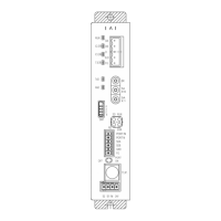
1. Gateway Unit
Item Specification
External Dimensions 30W × 115H × 95D [mm]
Mass Approx. 157g
2. Terminal Unit
Item Specification
External Dimensions 12.6W × 115H × 95D [mm]
Mass Approx. 49g
3. Linking Units
Item Specification
External Dimensions (42.6 + 22.6 × N) W × 115H × 95D [mm] N: Total number of driver units and extension units
Mass Approx. (206 + 180 × N1 + 99 × N2) g N1: Number of driver units, N2: Number of extensions units
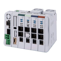
Installation and Noise Elimination
1. Noise Elimination Grounding (Frame Ground)
2. Precautions regarding wiring method
1) Wire is to be twisted for the 24V DC power supply.
2) Separate the signal and encoder lines from the power
supply and power lines.
3. Noise Sources and Elimination
Carry out noise elimination measures for electrical devices
on the same power path and in the same equipment.
The following are examples of measures to eliminate noise
sources.
1) AC solenoid valves, magnet switches and relays
[Measure] Install a Surge absorber parallel with the coil.
2) DC solenoid valves, magnet switches and relays
[Measure] Consider whether to attach a diode in parallel
to the coil or to use a diode built-in type.
4. Cooling Factors and Installation
Follow the specifications and dimensions shown below when you design and build a control board.
Item Specification Item Specification
Installation
Orientation
Vertical Orientation
(Air outlet upwards)
Surrounding Air
Temperature
0 to 55°C (Refer to section of
“Current Amperage” in ME0383)
Derating equipped when with no
fan unit
Installation
Method
Attached on DIN Rails
Installation
Condition
See figure below Grounding Class D grounding
* Simple absolute units can be installed in close contact with each other.
Installation Environment
This product is capable for use in the environment of pollution degree 2
*1
or equivalent.
*1 Pollution Degree 2: Environment that may cause non-conductive pollution or transient conductive
pollution by frost (IEC60664-1)
1. Installation Environment
Do not use this product in the following environment.
• Location where the ambient temperature is out of the range between 0 and 55°C (with fan) or
0 and 40°C (with no fan)
• Location where condensation occurs due to abrupt temperature changes
• Location where relative humidity exceeds 85%RH
• Location exposed to corrosive gases or combustible gases
• Location exposed to significant amount of dust, salt or iron powder
• Location subject to direct vibration or impact
• Location exposed to direct sunlight
• Location where the product may come in contact with water, oil or chemical droplets
• Environment that blocks the air vent [Refer to Installation and Noise Elimination]
When using the product in any of the locations specified below, provide a sufficient shield.
• Location subject to electrostatic noise
• Location where high electrical or magnetic field is present
• Location with the mains or power lines passing nearby
2. Storage and Preservation Environment
The storage and preservation environment should comply with the same standards as those for the
installation environment.
In particular, when the machine is to be stored for a long time, pay close attention to environmental
conditions so that no condensation forms. Unless specially specified, moisture absorbency protection is not
included in the package when the machine is delivered. In the case that the machine is to be stored and
preserved in an environment where condensation is anticipated, take the condensation preventive measures
from outside of the entire package, or directly after opening the package.
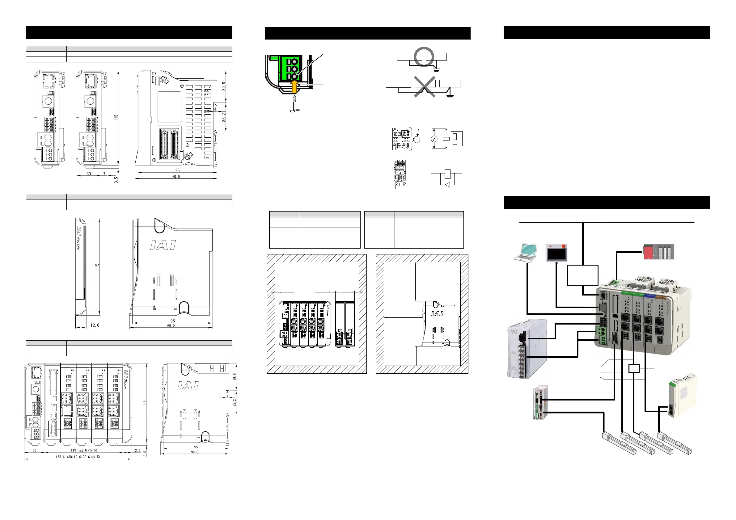
Connection to Peripheral Devices (Overall Wiring Diagram)
External Dimensions
Model Plate
(Large)
Adhered
Position
N: Total number of driver units and extension units
Do not share the ground wire with or connect
to other equipment. Ground each controller.
Controller
Other
equipment
Controller
Other
equipment
Other
equipment
Surge absorber
Relay
coil
Relay coil
R
C
+24V 0V
+24V 0V
+-
100mm or more
10mm
or more
100mm or more
50mm or more
Ceiling
RCON
Ceiling
10mm 10mm
Simple
Absolute
Unit
or more or more
Ethernet
connector
Field Network
(Cables to be prepared by
user)
Ethernet (Cables to be prepared by user)
USB Cable
(Cables to be
prepared by
user)
(Cables
to be
prepared
by user)
Communication Cable
Motor/encoder Cable
Model Code: CB-ADPC-MPA□□□(-RB)
SCON Cable
Model Code: CB-FC-CTL□□□
(Cables to be prepared by user)
Connector Conversion Unit
Model Code: RCM-CV-APCS
Simple Absolute Unit
+24V, 0V
SCON-CB-*-RC
PSA-24
PC
TB-02
TB-03 PLC
Actuator
 Loading...