Wiring Layout for Motor/Encoder Cables
Note 1 The 200V Servo Motor Actuators below are not capable to be connected to the 200V Driver Units.
(1) Motor types other than those from 60W to 750W
(2) Encoder types other than Battery-less Absolute, Incremental, Spurious Absolute and Index Absolute
(3) For Three-phase 200V, combination that exceeds 2400W in total of Actuator Wattages connected to
200V Driver Units
(4) For Single-phase 200V, combination that exceeds 1600W in total of Actuator Wattages connected to
200V Driver Units
(5) Servo Pressing Type
(6) SCARA Robot
(7) CT4 Series
(8) ZR Series
When it is necessary to connect actuators from (1) to (4) above, use the SCON Extension Unit and
SCON-CB.
Also, DD/DDA and LSA-W21S are not conformed with Single-phase 200V
Note 2 There is a built-in regenerative resistor of 60W equipped in 200V Driver Unit and 200V Power
Supply Unit.
The regenerative resistor is basically not necessary, but use this External Regenerative Resistor
Unit in case of shortage in regenerative resistance.
200V Driver Unit Connection Cable List
No.
Actuator
Series Target type Motor cable Motor robot cable Encoder cable Encoder robot cable
(1)
RCS4
RCS4CR
CB-RCC1-MA□□□ CB-X2-MA□□□ ― CB-X1-PA□□□
(2)
RCS3(P)
RCS3(P)CR
CTZ5C
CT8C
CB-RCC1-MA□□□ CB-X2-MA□□□
― CB-X1-PA□□□
Those other than above CB-RCS2-PA□□□ CB-X3-PA□□□
(3)
RCS2
RCS2CR
RCS2W
RTC□L
RT6
CB-RCC1-MA□□□ CB-X2-MA□□□
CB-RCS2-PLA□□□ CB-X2-PA□□□
Those other than above CB-RCS2-PA□□□ CB-X3-PA□□□
(4) RCS2
with no loadcell
equipped
RA13R
CB-RCC1-MA□□□ CB-X2-MA□□□
CB-X2-PLA□□□ CB-X2-PLA□□□
RA13R
with brake
(with brake box)
[Between Actuator and
Brake Box]
CB-RCS2-PLA□□□
[Brake Box and controller]
CB-RCS2-PLA□□□
[Between Actuator and
Brake Box]
CB-X2-PLA□□□
[Brake Box and controller]
CB-X2-PLA□□□
RA13R
with brake
(with no brake box)
[Between Actuator and
Brake Box]
CB-RCS2-PLA□□□
[Between Actuator and
Brake Box]
CB-X2-PLA□□□
(5)
IS(P)B
IS(P)DB
IS(P)DBCR
― CB-X2-MA□□□ ―
CB-X1-PA□□□
* For cable length 21m or
more and 30m or less in
battery-less absolute type;
CB-X1-PA□□□-AWG24
Option:
with limit switch type
CB-X1-PLA□□□
* For cable length 21m or
more and 30m or less in
battery-less absolute type;
CB-X1-PLA□□□-AWG24
(6)
IS(P)A
IS(P)DA
IS(P)DACR
SSPA
SSPDACR
IF
FS
RS
― CB-X2-MA□□□ ―
CB-X1-PA□□□
Option:
with limit switch type
CB-X1-PLA□□□
(7) NSA ― CB-X2-MA□□□ ― CB-X1-PA□□□
(8) NS
― CB-X2-MA□□□ ―
CB-X3-PA□□□
Option:
with limit switch type
CB-X2-PLA□□□
(9)
DD(A)
DD(A)CR
DDW
T18□
LT18□
―
CB-X2-MA□□□
― CB-X3-PA□□□
H18□
LH18□
CB-XMC1-MA□□□
(10) LSA
W□□□
―
CB-XMC1-MA□□□
―
CB-X2-PLA□□□
Those other than above CB-X2-MA□□□ CB-X3-PA□□□
(11) LSAS ― CB-X2-MA□□□ ― CB-X1-PA□□□
(12) IS(P)WA ― CB-XEU1-MA□□□ ― CB-X1-PA□□□-WC
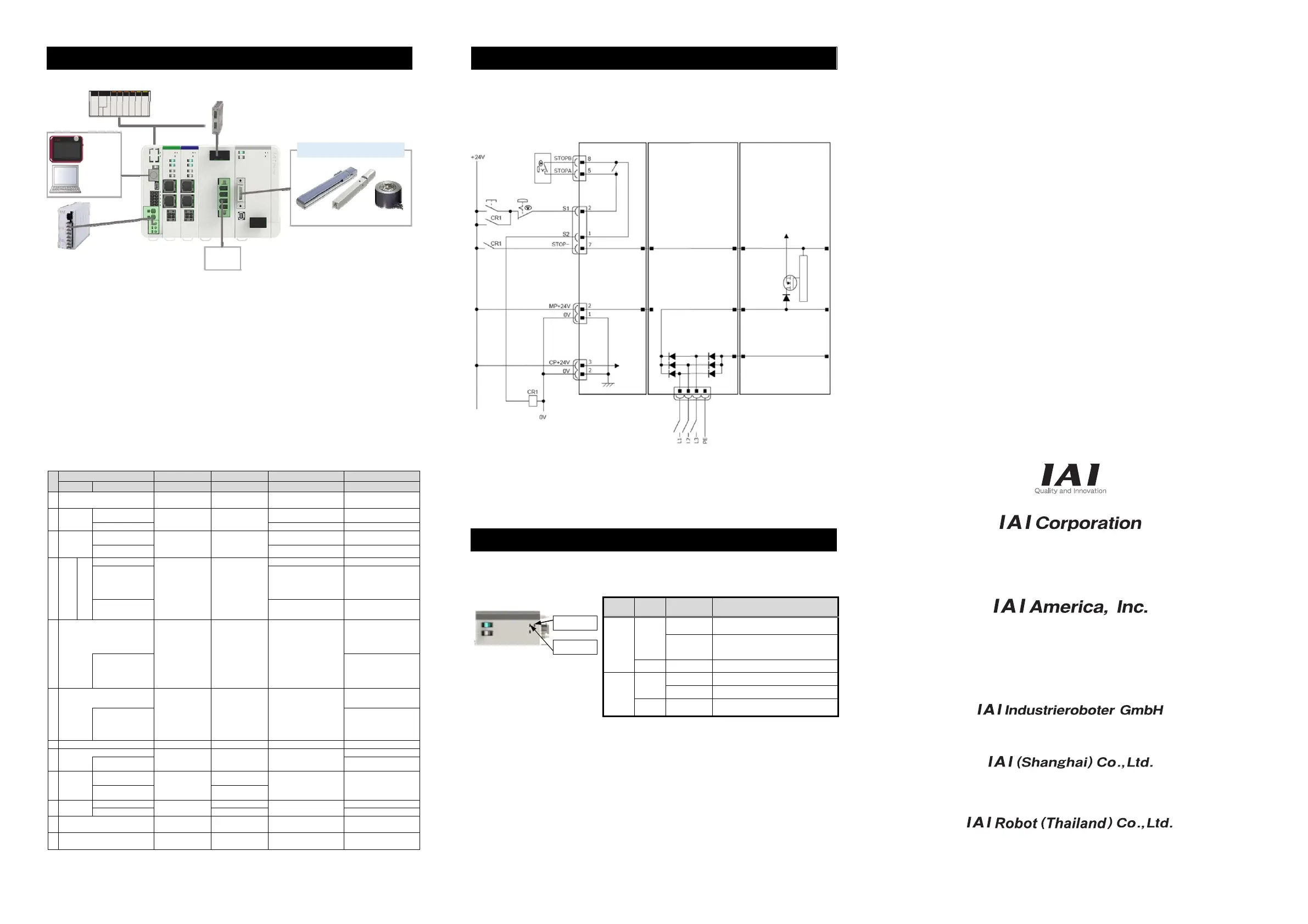
Power Supply and Stop Circuit (Example)
In the diagram below shows a circuit related to RCON drive source cutoff. The 200V Motor Power Supply is
a supply to the 200V Power Supply Unit. The circuit related to the drive-source cutoff is on the driver unit
side.
Each driver unit possesses a drive source cutoff circuit by semiconductor. The motor power should be
cut off by STOP Signal. The drive source cutoff circuit by semiconductor possesses features to detect
the overcurrent and to limit the in-rush current.
Note 1 RCON-GW : If nothing is connected to the SIO connector, S1 and S2 will be short-circuited in the controller.
RCON-GWG : If nothing is connected to the SIO connector, S1 and S2 will not be short-circuited in the controller.
To short-circuit, connect the supplied dummy plug DP-5 to the SIO connector.
Note ● Consider the cable diameter and length that would not drop the voltage for the drive-source cutoff connector wiring.
● There could be a case that the voltage drops on the controller power supply and generate an alarm due to the cable
diameter and length. In such a case, adjust the output voltage on the power supply so the voltage supplied to the
controller is kept at 24V.
Troubleshooting (LED Display)
In this section, describes for LED.
Utilize them to check normal operation status and recovery after error occurrence.
(1) 200V Driver Unit
Panel
Display
Color Status Explanation
T RUN
GN
Illuminating
Inside bus communication in
normal conditions
Flashing
Waiting for initializing
communication,
Initializing communication erro
OR Illuminating Inside bus communication in error
SYS
GN
Illuminating Turning servo ON
OFF Turning servo OFF
RD Illuminating
Alarm being generated, STOP
signal input ON
Head Office: 577-1 Obane Shimizu-KU Shizuoka City Shizuoka 424-0103, Japan
TEL +81-54-364-5105 FAX +81-54-364-2589
website: www.iai-robot.co.jp/
Ober der Röth 4, D-65824 Schwalbach am Taunus, Germany
TEL 06196-88950 FAX 06196-889524
SHANGHAI JIAHUA BUSINESS CENTER A8-303, 808, Hongqiao Rd. Shanghai 200030, China
TEL 021-6448-4753 FAX 021-6448-3992
website: www.iai-robot.com
Technical Support available in USA, Europe and China
Head Office: 2690 W. 237th Street, Torrance, CA 90505
TEL (310) 891-6015 FAX (310) 891-0815
Chicago Office: 110 East State Parkway, Schaumburg, IL 60173
TEL(847) 908-1400 FAX (847) 908-1399
TEL (678) 354-9470 FAX (678) 354-9471
website: www.intelligentactuator.com
Atlanta Office: 1220 Kennestone Circle, Suite 108, Marietta, GA 30066
825 PhairojKijja Tower 7th Floor, Debaratana RD., Bangna-Nuea, Bangna, Bangkok 10260, Thailand
TEL +66-2-361-4458 FAX +66-2-361-4456
website:www.iai-gmbh.de
website:www.iai-robot.co.th
Manual No.: ME0397-1B
T RUN LED
SYS LED
Power Supply Cable
(Cables to be prepared by
customer)
* Use cable with diameter large
enou
h to accept current.
Field Network
Connectable Actuators
o
e
PLC
Regenerative Resistances Unit
(Note 2)
RESU-2/RESUD-2
PSA-24
Power Supply
Unit
TB-02
TB-03
IA-101-X
IA-101-N
RCU-101-MW
RCM-101-USB
Single-phase
/Three-phase
AC200V
Gateway Unit 200V Power Supply Unit 200V Driver Unit
SIO Connector
System I/O
Connector
Motor Power Supply
Connector
for P/A/D Drivers
Control
Power
Connector
Note 1
Control
Power
Emergency
Stop Reset
Switch
Emergency
Stop Switch
Stop Switch on
Teaching Pendant
Motor Power Supply
Connector
Motor Power Supply
High-Side Protection Circuit
 Loading...