Surge absorber
R
C
+24V 0V
+24V 0V
+-
45.2 1
39.6
4
115
35.2
95
3.5
98.8
7
103.5
3. 200V Driver Unit
Item Specification
External Dimensions 45.2W × 115H × 95D [mm]
Mass Approx. 438g (fan unit weight excluded)
4. Fan Unit for 200V Driver Unit
Item Specification
External Dimensions 44.5W × 64H × 12.5D [mm]
Mass Approx. 20g
5. Terminal Unit for 200V
Item Specification
External Dimensions 12.6W × 115H × 95D [mm]
Mass Approx. 40g
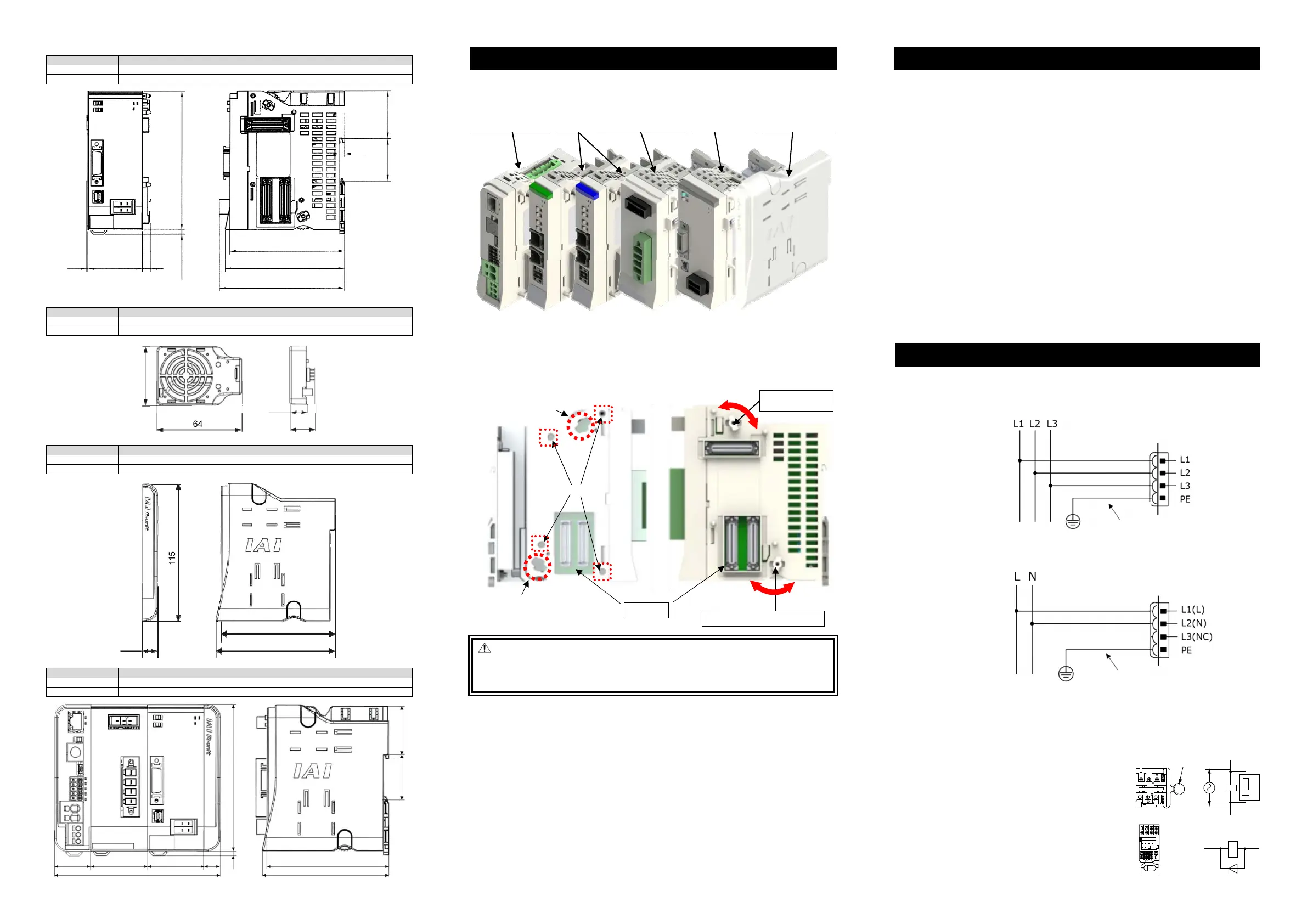
6. Linking Units
Item Specification
External Dimensions (30 + 45.2 + 45.2 + 12.6) W × 115H × 95D [mm]
Mass Approx. 1,077g
RCON/RSEL Systems possesses a locking structure with unit linking system. The 200V Power Supply Unit
is to be linked on the right of the 24V Driver Unit in the front view. The 200V Driver Units are to be linked on
the right of them for the necessary number of units, and the Terminal Unit for 200V come on the further right.
For the terminal unit, make sure to use the Terminal Unit for 200V enclosed to the 200V Power Supply Unit.
Gateway Unit (Left End) - Driver Unit - Power Supply Unit for 200V - Driver Unit for 200V - Terminal Unit for 200V
Unit should be linked in the process shown below. (Make sure it gets linked before connected to the DIN rails.)
1) Twist the operation parts of the link upper parts and the link bottom parts towards the panel side and
place them at the panel side end.
2) Adjust the position of two units so the link upper parts come to Point [A], link bottom parts to [B] and the
four positioning bosses to [C] and all the six points fit to each other.
3) Once positioning is done, firmly insert the connectors at two points.
4) Twist the operation parts of the link upper parts and the link bottom parts towards the rear side till they
make click feeling.
Danger: When there is a unit of 200V, make sure that the terminal unit on the right is the Terminal
Unit for 200V (RCON-GW-TRS) enclosed to the 200V Power Supply Unit. The Terminal
Unit for 24V has a structure that does not allow itself connected to the 200V units,
however, it could be forcefully inserted, which could cause fire on the connector as well as
damage on it.
Installation Environment
This product is capable for use in the environment of pollution degree 2
*1
or equivalent.
*1 Pollution Degree 2: Environment that may cause non-conductive pollution or transient conductive
pollution by frost (IEC60664-1)
1. Installation Environment
Do not use this product in the following environment.
Location where the ambient temperature is out of the range between 0 and 40C
Location where condensation occurs due to abrupt temperature changes
Location where relative humidity exceeds 85%RH
Location exposed to corrosive gases or combustible gases
Location exposed to significant amount of dust, salt or iron powder
Location subject to direct vibration or impact
Location exposed to direct sunlight
Location where the product may come in contact with water, oil or chemical droplets
Environment that blocks the air vent Refer to [Installation and Noise Elimination]
When using the product in any of the locations specified below, provide a sufficient shield.
Location subject to electrostatic noise
Location where high electrical or magnetic field is present
Location with the mains or power lines passing nearby
2. Storage and Preservation Environment
The storage and preservation environment should comply with the same standards as those for the
installation environment. However, the ambient temperature should be from -20 to 70°C and relative
humidity at 85%RH or below. In particular, when the machine is to be stored for a long time, pay close
attention to environmental conditions so that no condensation forms.
Unless specially specified, moisture absorbency protection is not included in the package when the machine
is delivered. In the case that the machine is to be stored and preserved in an environment where
condensation is anticipated, take the condensation preventive measures from outside of the entire package,
or directly after opening the package.
Installation and Noise Elimination
1. Protective Ground
For the grounding, the grounding resistance should be set to 100Ω or less (Class D grounding).
The wiring should apply a twist line or an annealed copper wire of 2.0mm
2
(AWG14) or more with an
isolation sheath with its rated temperature at 60°C or higher.
[200V
Three-phase Type]
[200V Single-phase Type]
2. Noise Elimination Grounding (Frame Ground)
Noise elimination grounding (frame ground) is conducted on the gateway unit side.
3. Precautions regarding wiring method
Separate I/O lines, communication lines and encoders, power source and supply lines from each other to
reduce the influence to each other.
4. Noise Sources and Elimination
Carry out noise elimination measures for electrical devices
on the same power path and in the same equipment.
The following are examples of measures to eliminate noise
sources.
1) AC solenoid valves, magnet switches and relays
[Measure] Install a Surge absorber parallel with the coil.
2) DC solenoid valves, magnet switches and relays
[Measure] Consider whether to attach a diode in parallel
to the coil or to use a diode built-in type.
Linking Units
Rear Side (Link)
Link Upper Parts
Operation Part
[C]
[A]
Link Bottom Parts Operation Part
[B]
Connector
Panel Side
(Unlink)
Rear Side
(Link)
Panel Side
(Unlink)
64
44.5
18.4
12.5
115
12.6
95
98.8
95
98.8
35.2
39.6
4
45.2
45.2
30
133
12.6
115
Motor Power Supply Connector
for 200V Motor Driving
Grounding resistance
at 100
Ω
or less
(Class D grounding)
St rand or annealed copper wire:
Connect with an eart h line of
2.0mm
2
(AWG14)ormore
Motor Power Supply Connector
for 200V Motor Driving
Grounding resistance
at 100
Ω
or less
(Class D grounding)
St rand or annealed copper wire:
Connect with an eart h line of
2.0mm
2
(AWG14) or more
 Loading...