Current Amperage
The current amperage should be divided into the control power capacity and motor power capacity.
In this guide, describes about the current amperage of the control power supply and 200V motor power
supply. For the current amperage of the 24V motor power supply, refer to the first step guide (ME0383) and
instruction manual (DVD) of RCON 24V Driver Unit.
The control power supply should be input from the control power supply connector on the gateway unit. The
motor power supply should be input from the 200V input connector on the 200V power supply unit.
The specifications related to the power capacities should be as shown below.
[Control Power Supply]
Item Specification
Power Supply Voltage 24V DC ±10%
Control Power Capacity
(for one unit)
Gateway unit
(terminal unit included)
RCON Gateway Unit
0.8A (Ethernet option: Not equipped)
1.0A (Ethernet option: Equipped)
SEL Unit 1.2A
24V Driver unit
Brake: Not equipped 0.2A
Brake: Equipped (one-axis type) 0.4A
Brake: Equipped (two-axis type) 0.6A
200V Driver uni
(200V power supply
unit included)
Brake: Not equipped 0.2A
Brake: Equipped 0.5A
Extension unit
SCON Extension Unit 0.1A
PIO/SIO/SCON Extension Unit 0.3A
PIO Unit 0.2A
Simple absolute unit (in common for all types) 0.2A
EC Connection Unit 0.1A
[200V Motor Power Supply]
Actuator Motor Wattage Motor Power Capacity Peek Max. Motor Power Capacity
60 138 414
60 (RCS3-CTZ5) 197 591
100 234 702
100S (LSA) 283 851
150 328 984
200 421 1263
200S (DD) 503 1509
200S (Excluding LSA (S)-N15H) 486 1458
200S (LSA (S)-N15H) 773 2319
300S(LSA) 662 1986
400 920 2760
400 (RCS3-CT8) 1230 3690
600 1164 2328
600 (DD) 1462 4386
750 1521 3042
750S 1521 4563
Restrictions in Unit Connection
(1) Current Restrictions
Shown below is the restricting values of current for selecting calculation.
Item Restricting Value of Current for Selecting Calculation
Control Power Supply (CP) 9.0A or less
The capacity necessary in the control power supply should be figured out by [Total of control power
capacity of used units].
In the table of the capacity [Control Power Supply] shown above, add the power capacity of all the units
constructing the system and check that it does not exceed the restricting values of current for selecting
calculation described in Restrictions in Unit Connection.
Also, the gateway units should not be included for the calculation.
Shown below is some examples for calculation.
[Control Power Supply] * The gateway units should not be included for the calculation.
Example 1
200V Actuator × 8 axes, All axes equipped with brake
200V Driver unit (with brake) 0.5A × 8 = 4.0A ⇒ OK
Example 2
200V Actuator × 16 axes, All axes equipped with brake
200V Driver unit (with brake) 0.5A × 16 = 8.0A ⇒ OK
Example 3
24V Actuator × 8 axes, All axes equipped with brake (2 axes/unit), All axes simple absolute type
200V Actuator × 8 axes, All axes equipped with brake
24V Driver unit (with brake) 0.6A × 4 + Simple absolute 0.2A × 8
+200V Driver unit (with brake) 0.5A × 8 = 8.0A ⇒ OK
Example 4
200V Actuator × 16 axes, All axes equipped with brake + PIO/SIO/SCON Extension Unit one unit, PIO Unit 7 units
200V Driver unit (with brake) 0.5A × 16 +
PIO/SIO/SCON Extension Unit 0.3A × 1 + PIO Unit 0.2A × 7 = 9.7A ⇒ NG
(2) 200V Motor Power Supply Current Restrictions
Shown below is the restricting values for selecting calculation.
Item
Restricting Value for Selecting Calculation
200V Motor Power Supply (Single-phase)
1600W
200V Motor Power Supply (Three-phase)
2400W
The capacity necessary in the motor power supply should be figured out by [Total of control power
capacity of used units].
In the table of the capacity [Motor Power Supply] shown above, add the power capacity of all the actuator
motor wattages constructing the system and check that it does not exceed the restricting values of
current for selecting calculation described in Restrictions in Unit Connection.
However, apply the motor wattage for calculation for the actuators listed below.
Actuator Model Code
Motor Wattage for
Calculation
RCS3-CTZ5 120W
LSA-S6S□/S8S□/S8H□/N10S□ 300W / 1 Slider
LSA-S10SM/H8SM/H8HM/L15SM/N15SM/N15HM/N19SM 400W / 1 Slider
LSA-S10SS/S10HS/H8SS/H8HS/L15SS/N15SS/N15HS/N19SS
600W
LSA-W21S□、RCS3-CT8 800W / 1 Slider
Shown below is some examples for calculation.
[200V Motor Power Supply]
Example 5
One axis for each of actuator of 200W motor, actuator of 300W motor and actuator of 600W
moto
200W × 1 axis + 300W ×1 axis + 600W × 1 axis = 1100W
⇒
Single-phase OK, Three-phase OK
Example 6
RCS-CTZ5 × 1 axis, actuator of 200W motor × 7 axes
120W + 200W × 7 axes = 1520W⇒ Single-phase OK, Three-phase OK
Example 7
actuator of 200W motor × 6 axes, LSA-S10SM (Multiple Slider) × 1 axis
200W × 6 axes + 400W × 2 = 2000W ⇒ Single-phase NG, Three-phase OK
Example 8
actuator of 200W motor × 16 axes
200W × 16 axes = 3200W ⇒ Single-phase NG, Three-phase NG
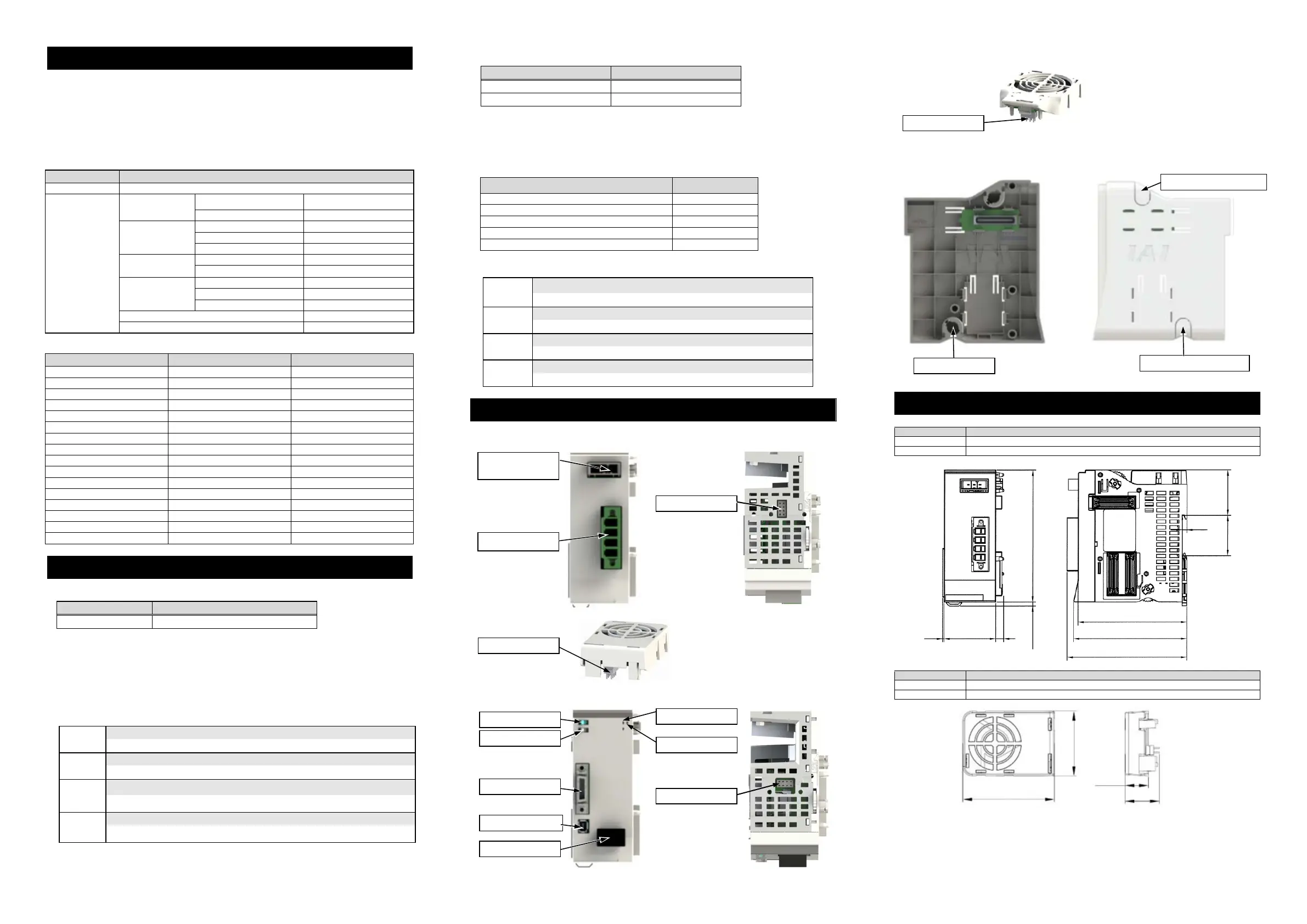
(1) 200V Power Supply Unit
Front Top
(2) Fan Unit
(3) 200V Driver Unit
Front Top
(4) Fan Unit for 200V Driver
(5) Terminal Unit for 200V
Left Side Right Side
1. 200V Power Supply Unit
Item Specification
External Dimensions 45.2W × 115H × 95D [mm]
Mass Approx. 393g (fan unit weight excluded)
2. Fan Unit
Item Specification
External Dimensions 34.2W × 49H × 12.5D [mm]
Mass Approx. 16g
Names for Each Part
External Dimensions
External
Regenerative
Connector
200V AC
Input Connector
FAN Connector
FAN Connector
FAN Connector
Jog Switch
Brake Switch
Encoder Connector
Driver Stop Connector
SYS LED
T RUN LED
Motor Connector
Fan Connector
Bottom Parts for Terminal Unit
Upper Parts for Terminal Unit
34.2
49
12.5
18.4
115 3.5
7
45.2
39.6
4
35.2
95
1
98.8
104.5
Linked Connector
 Loading...