Do you have a question about the IBA ibaMS8xIEPE and is the answer not in the manual?
Defines the intended audience of the manual, focusing on qualified professionals.
Explains the various notations, keys, and commands used throughout the document.
Defines safety and informational symbols, including DANGER, WARNING, CAUTION, and NOTES.
Specifies authorized applications and general usage guidelines for the device.
Lists critical safety warnings, such as handling live voltage and inserting modules.
Lists the required central units and backplane units for system compatibility.
Specifies the necessary software versions, including ibaPDA and ibaLogic.
Step-by-step instructions for physically installing the module onto the backplane.
Procedures for making electrical connections and powering up the system.
Instructions for safely detaching and removing the module from the backplane.
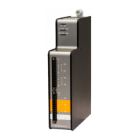
Identifies physical components and connectors on the front of the device.
Explains the function of LEDs for device and input status.
Details the meaning of the device status LEDs (L1-L4) and their indications.
Describes the LED status for IEPE input channels and their operating modes.
Covers configuration options, settling times, and operating modes for analog inputs.
Explains the RC high-pass and anti-aliasing filters, including cutoff frequencies.
Illustrates the wiring and pinout for the 8 analog input channels.
Details the available error and status signals in different operating modes.
Explains the "data valid" signal indicating completion of the settling process.
Describes the detection and signaling of broken lines or disconnected sensors.
Explains the detection and signaling of short circuits on input channels.
Describes the automatic software update process upon initial device startup.
Explains the system's overall release version and its significance.
Outlines the two methods for updating the module's firmware: Web interface and ibaPDA.
Provides step-by-step instructions for firmware updates using the web interface.
Details the process for updating firmware using the ibaPDA software's I/O Manager.
Explains how to access hardware, firmware, and serial number information via ibaPDA.
Describes accessing general module information via the web interface.
Details the general information and technical specifications displayed in the module's "info" tab.
Explains how to use the "notes" tab to store personal comments or linkage data.
Guides on configuring the module's signals and settings using the ibaPDA I/O Manager.
Covers setting up general module parameters like Name, Module No., and Timebase in ibaPDA.
Describes how to configure analog input channels, including mode selection and filters.
Explains how to enable and configure error and status signals in the "Digital" tab.
Details signal configuration within the ibaLogic-V5 I/O Configurator.
Provides core specifications like product name, description, order number, and power details.
Details specifications for the analog input channels, including number, design, resolution, and IEPE details.
Shows physical dimensions and provides drawings of the module for installation planning.
Provides contact information for technical support, including phone, fax, and email.
Lists headquarters, mailing, and delivery addresses of the manufacturer.
| Category | I/O Systems |
|---|---|
| Channels | 8 |
| Supply Voltage | 24 V DC |
| ADC Resolution | 24-bit |
| Input Range | ±10 V |
| Form Factor | Modular |
| Input Type | IEPE |
| Power Supply | 24 V DC |