RAID Technology
BayBay
ArrayArray
Ch 2Ch 1
Bay
Array
1
2
3
4
5
6
7
8
9
10
11
12
13
14
15
1
2
3
4
5
6
7
8
9
10
11
12
13
14
15
1
2
3
4
5
6
7
8
9
10
11
12
13
14
15
Ch 1 Ch 2 Ch 3
CDR
TAP
SHS
A
A
ONL
ONL
B
B
D
D
D
D
D
D
C
C
HSP
DHS
ONL
DDD
ONL
A
A
ONL
ONL
B
B
C
C
A
ONL
B
ONL
ONL
ONL
ONL
ONL
ONL
ONL
ONL
ONL
ONL
ONL
ONL
ONL
ONL
A
ONL
B
RBL
RDY
C
C
1. Help
2. Delete Disk Array
3. Create Disk Array
4. Define Logical Drive
5. Delete Logical Drive
Enter a value greater than 2 and less than the default value shown or 32X1024
whichever is lesser, and press Enter. ESC to quit.
Create/Delete Array
Array
ID
Size(MB)
Log
Drv
Size
(MB)
RAID
Level
Date
Created
Status
WRT
Pol
A0
A1
A2
B0
B1
C0
C1
1500
1500
1005
1500
3510
1500
1170
RAID-5
RAID-0
RAID-1
RAID-5
RAID-0
RAID-0
RAID-1
03/24/94
03/24/94
03/24/94
03/24/94
03/24/94
03/24/94
03/24/94
OKY
OKY
OKY
OFL
OFL
OKY
OKY
WT
WT
WT
WT
WT
WB
WT
A
B
C
D
5760
5760
3840
5760
Enter Size
of Logical
Drive,(MB)
:3840
12
3
6
5
4
IBM PC ServeRAID Adapter Disk Array Configuration Ver. 1.XX
Adapter Number: 1 Bus Number: 0 Host ID = Null Config
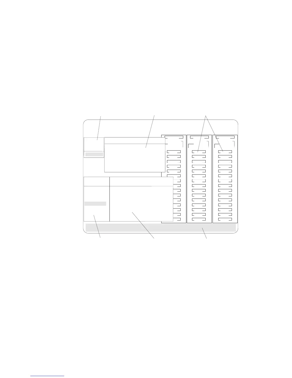
1. This area displays pop-ups that apply to the current menu. For
example, a pop-up allows you to select the logical drive size by
entering the size in megabytes; or, to accept the default value
shown. Another pop-up allows you to select the RAID level
you want to assign to the logical drive you are defining. When
you need to confirm an action, the Confirm pop-up appears in
this area.
2. You can select any of the choices that appear on the menus.
3. The Bay/Array selection list shows 15 bays for each of the
adapter's three channels. For each bay that contains a drive, the
list indicates the state of the physical drive and the array in
which the drive is grouped. For example, in the illustration, the
drive in Channel 2, Bay 1, has a drive status of ONL and is a
part of Array B. Selections are made from this list to determine
which bays (hard disk drives) are in your arrays.
84 PC Server 520 User's Handbook for PCI/EISA