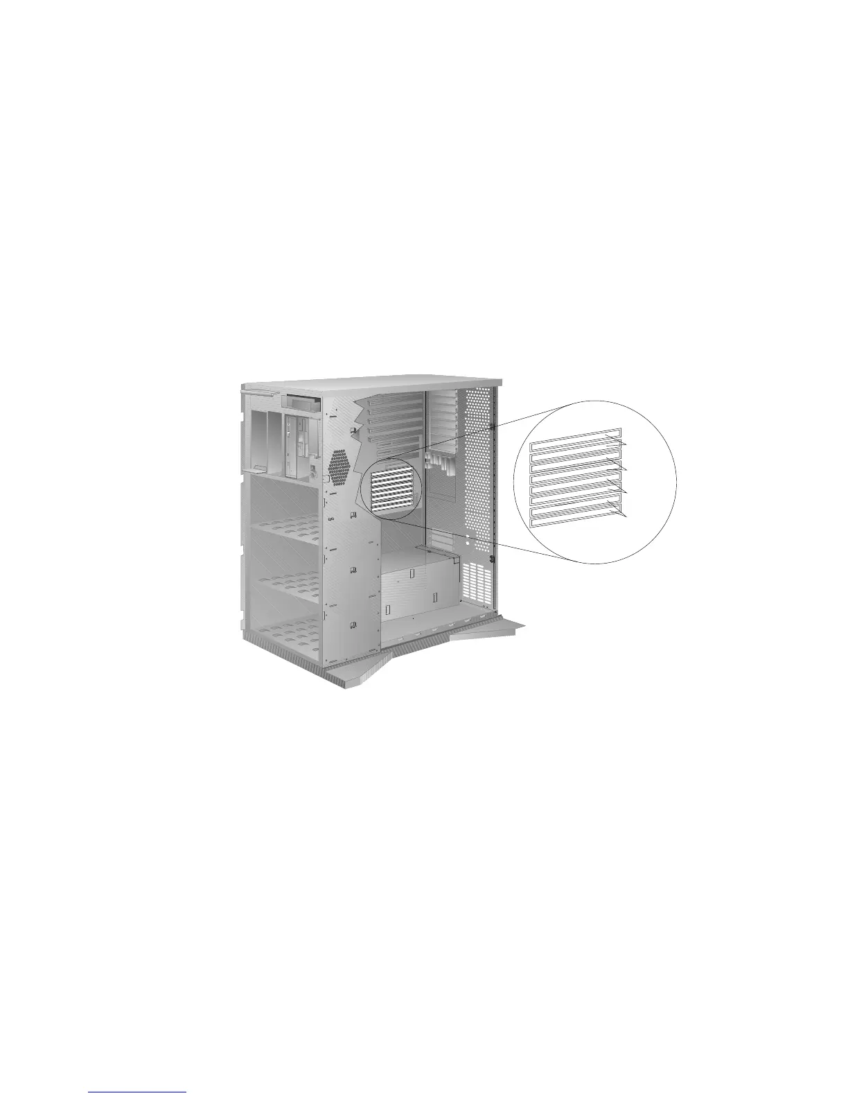
Installing Memory-Module Kits
The following illustration shows the memory-module connectors for
all models.
Bank 3
Bank 2
Bank 1
Bank 0
1. Locate the memory connectors on the system board.
When you are instructed to install the kits (in step 4 on
page 172), install them in pairs of adjacent memory connectors,
with no vacant memory connectors in between. Each pair of
connectors is a bank. Your server has four banks: 0, 1, 2, and 3.
Your server is shipped with two memory-module kits installed
in bank 0, located near the bottom of the system board. If
additional memory is required, install two kits in bank 1, and
then continue with banks 2 and 3, in that order. If you need to
install kits of a different size in bank 0, remove the preinstalled
kits as described in “Removing Memory-Module Kits” on
page 175, and install two other kits as described in this section.
As a minimum, your server requires memory modules of the
same size in bank 0. When you install memory-module kits in
any given bank, all of the kits in that bank must be the same
size.
170 PC Server 520 User's Handbook for PCI/EISA