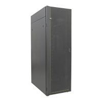
4
A side -48V DC input cable.
5
Cable channel cover retaining screw.
6
Cable channel cover.
7
Power distribution panel top cover retaining screw.
8
Power distribution panel top cover.
9
B-side shield.
10
A-side shield.
11
Power distribution panel.
12
Front of rack.
2. Remove the PDP top cover. To remove the top cover, perform the following steps:
a. Remove the four retaining screws (7).
b. Remove the PDP cover.
3. Remove the A and B side plastic bus bar covers from the PDP. To remove the plastic bus bar covers
from the PDP, perform the following tasks:
a. Remove the two retaining screws from the A side cover.
b. Remove the A side cover.
c. Remove the two retaining screws from the B side cover.
d. Remove the B side cover.
DANGER:
The bus bar covers must be correctly reinstalled to protect against possible injury when
maintenance is performed on the power distribution panel.
4. If you are using alarm circuity, perform the following steps to connect it now. If you are not using
alarm circuitry, continue with step 5.
Note: Ensure that the alarm wiring will not interfere with the installation of the left and right plastic
bus bar covers.
28
Power Systems: Racks and rack features

 Loading...