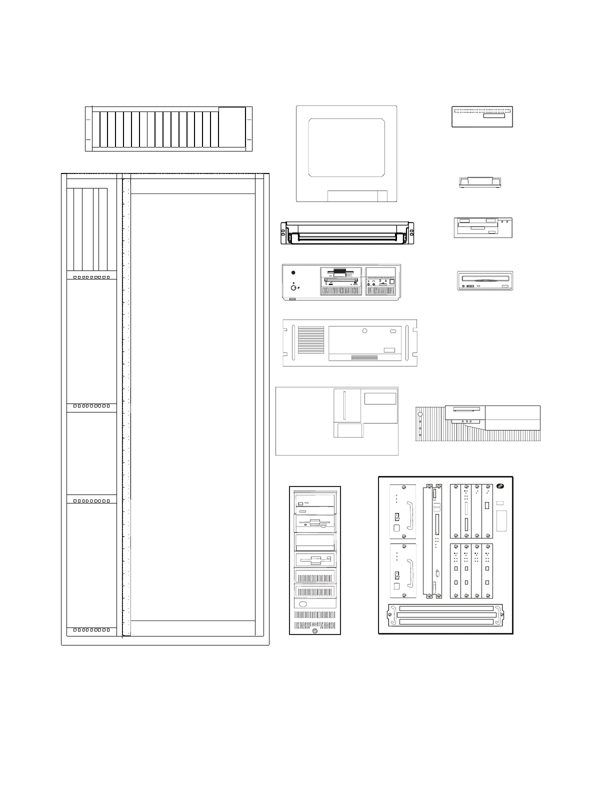
Use this drawing to setup the units on the front side of the controller expansion,
for the units that can be installed on the rear, refer to Figure D-2 on page D-3.
Display (8U)
SP and NNP: Type 3172 (6U)
SP and NNP: Type 6275 (4U)
SP and NNP: Type 7585 (4U)
SP: Type 9577 (4U)
Modems (2U)
7855
7857
7785
CD-ROM
Drive (2U)
Service Drawer (2U)
LCBB/LCBE (4U)
SP: Type 9685 (12U)
MAE (13U)
Controller Expansion (37U)
Front View
Optical Disk
Drive (2U)
Reserved for Cooling
Reserved for Cooling
Hayes
Modem (1U)
MR AA
V.34/V.FC+FAX+VOICE
CD
OPTIMA288
OH RD SD TR VO
YY
Y
Y
YY
Y
Y
Y
Y
Y
Figure D-1. Controller Expansion Inventory Chart (Front View).
D-2 3746-9X0: MAE Installation and Maintenance