Home
IBM
Power Supply
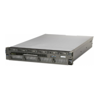
9009-42G
IBM 9009-42G - User Manual
28 pages
Manual
Specs
Ask a question
Save Page as PDF
To Next Page
To Next Page
Loading...
P
ower Systems
External DVD drive for the 5105-22E,
9008-22L, 9009-22A, 9009-22G,
9009-41A, 9009-41G, 9009-42A,
9009-42G, 9040-MR9, 9080-M9S,
9223-22H, 9223-22S, or 9223-42H,
9223-42S
IBM
2
Table of Contents
Main Page
Table of Contents
3
Safety Notices
5
External DVD Drive
15
Stand-Alone USB DVD Drive (FC EUA5)
15
Notices
17
Accessibility Features for IBM Power Systems Servers
18
Privacy Policy Considerations
19
Trademarks
19
Electronic Emission Notices
19
Class a Notices
19
Class B Notices
23
Terms and Conditions
25
Need help?
Do you have a question about the IBM 9009-42G and is the answer not in the manual?
Ask a question
IBM 9009-42G Specifications
Print Specification
General
Output Voltage
12V DC
Hot Swappable
Yes
Model
9009-42G
Input Voltage
200 to 240 V AC
Input Frequency
50 to 60 Hz
Compatibility
IBM Power Systems
Type
AC
Related product manuals
IBM 9009-41A
194 pages
IBM 9009-22A
150 pages
IBM 9080-M9S
730 pages
IBM 9117-MMB
114 pages
IBM 9117-MMA
82 pages
IBM 9223-22H
150 pages
IBM 9223-22S
150 pages
IBM 9223-42H
102 pages
IBM AC922
24 pages
IBM 3000VA
22 pages
IBM 5105-22E
150 pages
IBM Power System L922
40 pages