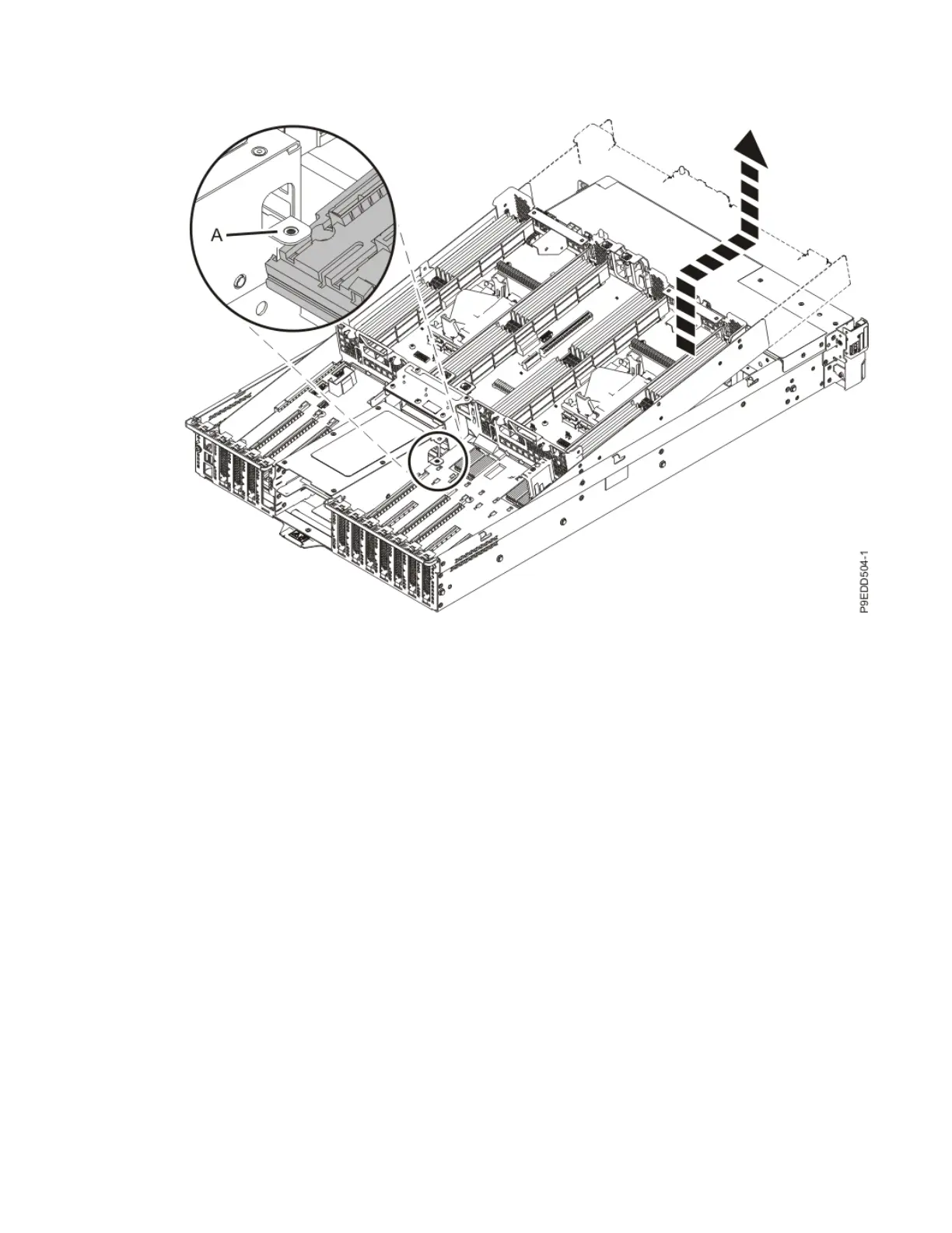
on the power supply cage, slide the system backplane forward until it clear the tabs. Then, lift the
system backplane completely out of the chassis. See the following gure.
Figure 61. Lifting the system backplane out of the chassis
g) Place the system backplane on an appropriate ESD surface.
28. Set the new system backplane on the ESD surface next to the system backplane you just removed.
29. Transfer the memory modules and llers to the new system backplane:
a) Unlock a memory module or ller from its connector by simultaneously pushing both of the
locking tabs away from the module in the direction that is shown in the following gure.
The lever action of the tabs pushes the memory module or ller out of the connector. If you nd it
difcult to open the tabs with your ngers, you may use the tips of ball point pens or the eraser
ends of pencils to open the tabs. The levers must be opened simultaneously, so that the memory
module lifts straight up.
62
Power Systems: System backplane
 Loading...