Remove SCM
To remove a SCM, complete the following steps:
1. When the node being serviced is above EIA location 29U, the ladders must be used while
installing or removing the rear and front FRUs and cables.
2. Perform the following procedure on ONLY THE FRU(s) BEING SERVICED. The following images
are generic and do not represent the literal location being serviced.
3. Modifying FRU locations which are not called out for service can have adverse effects on the
system, INCLUDING SYSTEM OUTAGE AND LOSS OF DATA.
4. The torque tool (P/N 41V1059) is required for this procedure. The torque tool was initially shipped
with the system.
5. CAUTION: If the system slide rails are installed above EIA location 29U, two Support Services
Representatives (SSRs) must perform the procedure together and the following equipment must be
used as a safety precaution for servicing: ServerLIFT tool (P/N 74Y4399), two Hard hats (P/N
5442867) and two service-qualified ladders (P/N 46G5947 and P/N 00E4866)
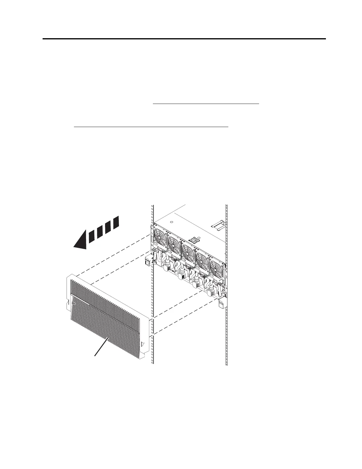
1. Remove front bezel
a. Remove the front bezel (A) from the system node being serviced and all system nodes which
share the same system control unit with the system node being serviced.
b. If present, remove the retention screws (A) from the front of the system node.
© Copyright IBM Corp. 2014 1