Switch Unit-Control Words Selected (depends upon
UCW
capacity
and
C
t
switch-A
setting)
0
0,16
32,48
64,80 96,112
128,144
160,176
192,208
1
1,17
33,49
65,81
97,113
129,145
161,177
193,209
2
2,18
34,50
66,82
98,114
130,146
162,178 194,210
3
3,19
35,51
67,83
99,115 131,147 163,179 195,211
4
4,20
36,52
68,84
100,116
132,148
164,180 196,212
5
5,21 37,53
69,85
101,117
133,149
165,181 197,213
6
6,22
38,54
70,86
102,118
134,150 166,182
198,214
7 7,23 39,55 71,87
103,119
135,151
167,183 199,215
8
8,24
40,56 72,88
104,120
136,152 168,184 200,216
9
9,25
41,57
73,89
105,121
137,153 169,185 201,217
A
10,26
42,58
74,90
106,122
138,154
170,186
202,218
B
11,27
43,59
75,91
107,123 139,155 171,187 203,219
C
12,28
44,60
76,92 108,124
140,156
172,188
204,220
D
13,29 45,61
77,93 109,125 141,157
173,189
205,221
E
14,30
46,62
78,94
110,126
142,158 174,190
206,222
F
15,31 47,63 79,95 111,127
143,159 175,191
207,223
Switch
A-
MPX
0
MPX
1
MPX
2
MPX
3
MPX
4
MPX
5
MPX
6
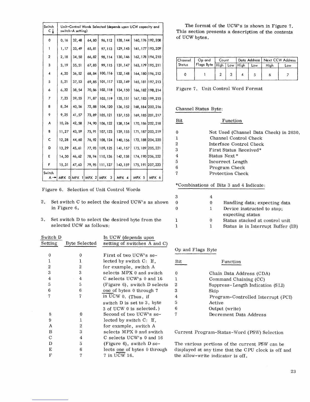
Figure
6.
Selection
of
Dnit
Control
Words
The
format
of
the
DCW's
is
shown
in
Figure
7.
This
section
presents
a
description
of
the
contents
of
DCW
bytes.
Channel
Op
and
Count
Data
Address
Next
CCW
Address
Status
Flags Byte
High
Low High
Low
High
Low
a 1 2
3
4
5
6
7
Figure
7.
Dnit
Control
Word
Format
Channel
Status
Byte:
Bit
o
1
2
3
4
5
6
7
Function
Not
Dsed
(Channel
Data
Check)
in
2030.
Channel
Control
Check
Interface
Control
Check
First
Status
Received
*
Status
Next
*
Incorrect
Length
Program
Check
Protection
Check
*Combinations
of
Bits
3
and
4
Indicate:
3
2.
Set
switch
C
to
select
the
desired
DC\V's
as
shown
0
4
o
1
Handling
data;
expecting
data
Device
instructed
to
stop;
expecting
status
in
Figure
6.
0
3.
Set
switch
D
to
select
the
desired
byte
from
the
1
o
1
Status
stacked
at
control
unit
Status
is
in
Interrupt
Buffer
(IB)
selected
DCW
as
follows:
1
Switch
D
In
DC\V
(depends
upon
Setting
Byte
Selected
setting
of
switches
A
and
C)
0 0
First
of
two
DCW's
se-
1 1
lected
by
switch
C:
If,
2
2
for
example,
switch
A
3 3
selects
MPX
0
and
switch
4 4
C
selects
DCW's
0
and
16
5 5
(Figure
6),
switch
D
selects
6 6
one
of
bytes
0
through
7
7 7
in
DCW
O.
(Thus,
if
switch
D
is
set
to
3,
byte
3
of
DCW 0
is
selected.)
8 0
Second
of
two
DCW's
se-
9
1
lected
by
switch
C:
If,
A 2
for
example,
switch
A
B 3
selects
MPX
0
and
switch
C 4
C
selects
DCW's
0
and
16
D
5
(Figure
6),
switch
D
se-
E
6
lects
~
of
bytes
0
through
F
7 7
in
DCW
16.
Op
and
Flags
Byte
Bit
o
1
2
3
4
5
6
7
Function
Chain
Data
Address
(CDA)
Command
Chaining
(CC)
Suppress-
Length
Indication
(S
LI)
Skip
Program-Controlled
Interrupt
(PCI)
Active
Output
(write)
Decrement
Data
Address
Current
Program-Status-Word
(PSW)
Selection
The
various
portions
of
the
current
PSW
can
be
displayed
at
any
time
that
the
CPD
clock
is
off
and
the
allow-write
indicator
is
off.
23

 Loading...