16
ECU 04/2015 rev.3
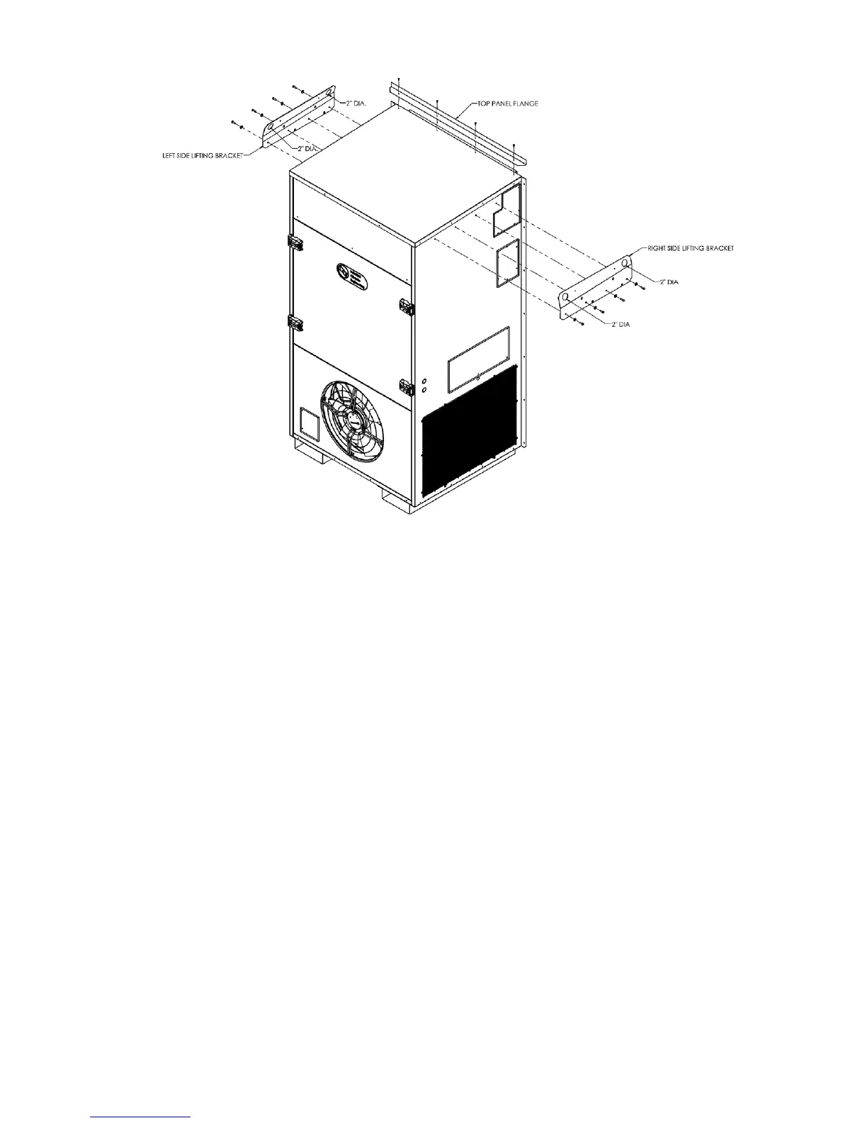
Figure 2. Top Flange and Lifting Bracket Installation
2.6 Installing the Lifting Brackets
The ECU90/120/150 have lifting brackets that can be installed on the top of the side panels. These
brackets allow the unit to be picked up thru lifting eyes in the brackets.The lifting brackets are shipped
attached to the back panel of the ECU. Attach the brackets to the left and right side panels as shown in
Figure 2. The 4 screws for attaching the brackets are shipped in the holes at the top of the side panels.
When attaching the brackets, make sure the top of the bracket is angled towards the center of the ECU.
2.7 Mounting The Unit
1. For wiring into the back of unit, locate the lower of the two knockouts on the wall side of the unit.
Drill a one inch hole in the shelter wall to match this opening. Allow sufcient clearance to run
3/4" conduit through the hole and to the unit.
2. Lift the unit into position using an appropriate and safe lifting device.
3. Make sure that the duct anges are properly aligned with the wall opening. Adjust as necessary.
4. Note the holes in each side ange. Using the holes for guides, drill holes through the wall with a
drill bit. Insert the bolts through the anges. Install nuts and washers on the inside of the shelter.
Tighten the bolts to secure the unit.
5. Apply a bead of silicone where the side and top anges contact the exterior wall.
6. On the inside of the shelter, install the wall sleeves in the supply and return air openings. The sleeves
may be trimmed to t ush with the inside wall.
7. Check the t of each sleeve to its mating ange for possible air leaks. Apply silicone sealer to close
any gaps. Install the air return and supply grilles.