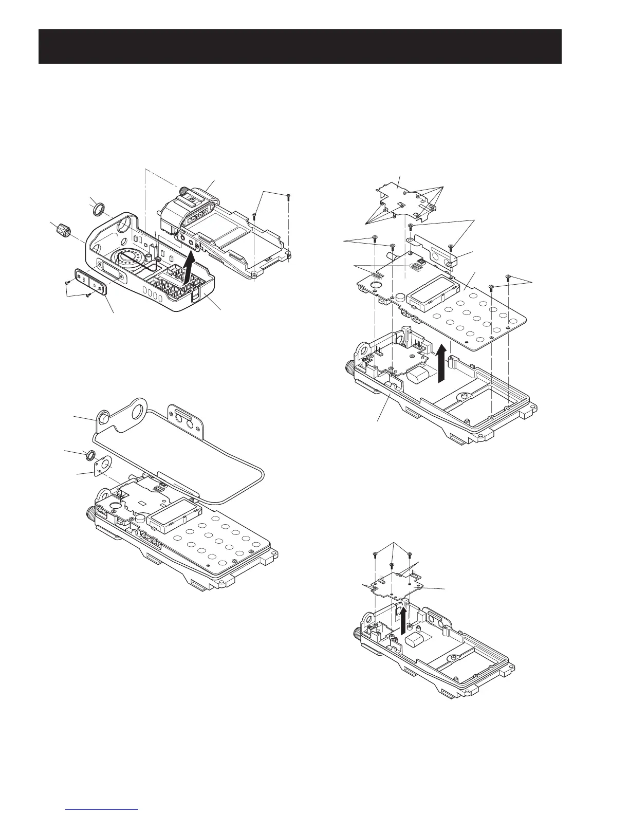
SECTION 3 DISASSEMBLY INSTRUCTIONS
3 - 1
2 REMOVING THE MAIN UNIT
q Remove the main seal F.
w Unscrew VR nut G, and remove the top plate H.
3 REMOVING THE PA UNIT
q Unscrew 3 screws M.
w Unsolder 4 points N, and take off the PA UNIT in the
direction of the arrow.
1 REMOVING THE CHASSIS UNIT
q Unscrew ANT nut A, and remove knob B.
w Unscrew 2 screws C, and remove the jack panel.
e Unscrew 2 screws D, and unplug the connector E from
the chassis unit.
r Take off the chassis unit in the direction of the arrow from
the front panel.
e Unscrew 6 screws J.
r Remove the side plate I.
t Unsolder 8 points K, and remove the shield cover.
y Unsolder 8 points L, and take off the MAIN UNIT in the
direction of the arrow.
(Continued to right above)
CHASSIS UNIT
Jack panel
Front panel
D
A
B
C
E
G
F
H
Shied cover
MAIN UNIT
K
K
J
L
× 8
J
J
I
CHASSIS UNIT
M
N
N
PA UNIT
 Loading...