3
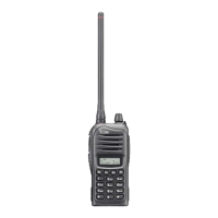
PANEL DESCRIPTION
2
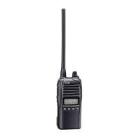
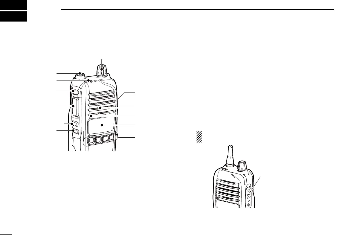
■ Front panel
q
w
r
e
u
y
Microphone
Speaker
t
i
q ANTENNA CONNECTOR
Connects the supplied antenna.
w DEALER-PROGRAMMABLE KEY [Emer]
Desired function can be programmed by your dealer.
(p. 7)
e DEALER-PROGRAMMABLE KEY [Side1]
Desired function can be programmed by your dealer.
(p. 5)
r PTT SWITCH [PTT]
Hold down to transmit.
Release to receive.
t DEALER-PROGRAMMABLE KEYS [Side2]/[Side3]
Desired functions can be programmed independently by
your dealer. (p. 5)
y DEALER-PROGRAMMABLE KEYS [P0] to [P3]
Desired functions can be programmed independently by
your dealer. (p. 5)
u FUNCTION DISPLAY (p. 4)
Displays a variety of information such as an operating
channel number/name, 2-Tone code, DTMF numbers,
selected function and so on.
i EXTERNAL MICROPHONE/SPEAKER JACK
Connect an optional speaker-microphone.
NOTE: Connect or disconnect the optional equipment
after the transceiver is turned OFF.
Jack cover
NOTE: Attach the jack
cover when the optional
equipment is not used.
Refer to page 2 for
details.
o VOLUME CONTROL [VOL]
Rotate to turn the power ON/OFF and adjusts the audio
level.
 Loading...